Optical isolation apparatus

A technology of optical emitter and detection of light, which is applied in the field of optical isolation and can solve the problem of sensor loss of function

Pending Publication Date: 2021-12-31
AMS INT
View PDF0 Cites 0 Cited by
  • Summary
  • Abstract
  • Description
  • Claims
  • Application Information

AI Technical Summary

Problems solved by technology

If the emitter signal is not attenuated or optically isolated from the sensor, the light generated by the emitter may blind the sensor

Method used


Image

  • Optical isolation apparatus
  • Optical isolation apparatus
  • Optical isolation apparatus

Examples


Embodiment approach

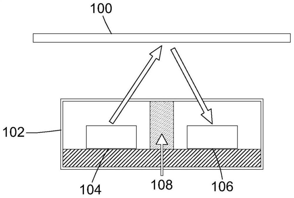
[0033] In general, the present disclosure eliminates the need for opaque mechanical barriers for optical isolation between optical emitters and sensors.

[0034] Some examples of solutions are given in the attached drawings.

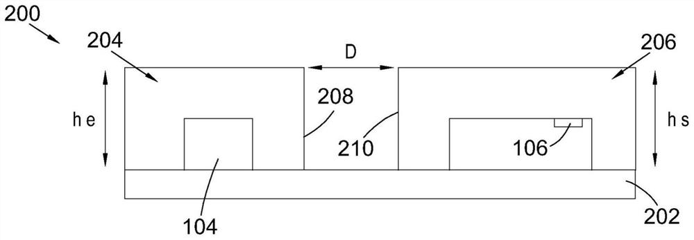
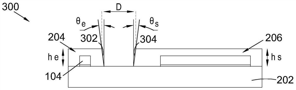
[0035] Embodiments described herein relate to a device that includes an optical emitter 104 mounted to a substrate 202 . A transparent emitter housing portion 204 surrounds the optical emitter 104 . Optical emitter 104 emits light (eg, infrared light). Optical transmitter 104 may be a laser diode, such as a vertical cavity surface emitting laser (VCSEL). It will be appreciated that the optical emitter 104 can be any light emitting component and is not limited to the examples mentioned herein. The device also includes a light sensor 106 for detecting light. A transparent sensor housing portion 206 surrounds the sensor 106 . Sensor 106 may be, for example, a photodiode. It will be appreciated that sensor 106 may be any light sensitive component and i...


PUM

PropertyMeasurementUnit
lengthaaaaaaaaaa

Abstract

An apparatus comprising: an optical emitter (104) mounted to a substrate (202); a transparent emitter housing portion (204) enclosing the optical emitter; a sensor (106) for detecting light, the sensor mounted to the substrate; a transparent sensor housing portion (206) enclosing the sensor; wherein the transparent emitter housing portion and the transparent sensor housing portion are horizontally separated on the substrate by an air gap.

Description

technical field [0001] The present disclosure relates to providing optical isolation between an optical emitter and a light sensor. Background technique [0002] Mobile phones and other portable computing devices often contain sensors to determine when objects are in the vicinity of the device. For example, many mobile phones use infrared proximity sensors to determine when a user is holding the phone close to their head for a phone call, so that the screen can be disabled to save power and to disable touching the screen. [0003] A proximity sensor module, for example, uses an emitter to bounce light off nearby objects and a sensor to detect the reflected light. Proximity sensors of mobile phones are very small modules and the transmitter is usually placed quite close to the sensor. If the emitter signal is not attenuated or optically isolated from the sensor, the light generated by the emitter may blind the sensor. [0004] A known proximity sensor module 102 is shown i...

Claims


Application Information

Patent Timeline
Patent Type & Authority Applications(China)
IPC IPC(8): G01S17/04G01S7/481H01L31/173
CPCG01S17/04G01S7/4813H01L31/173G01S7/4814G01S7/4816H01L31/0203
Inventor D.沃伦L.霍尔M.霍夫斯泰特
Owner AMS INT
Why Eureka
Try Eureka