
Cartridge receiver and fluid power equipment

A fluid power and equipment technology, applied in the field of casing and fluid power equipment, can solve the problems of the influence of the flow field structure, the axial and circumferential dimensions of the large perforation rate, and the efficiency loss, so as to reduce the blade load and solve the gap leakage flow. , the effect of expanding the stable operation margin

Pending Publication Date: 2022-01-04
BEIHANG UNIV
View PDF10 Cites 0 Cited by
  • Summary
  • Abstract
  • Description
  • Claims
  • Application Information

AI Technical Summary

Problems solved by technology

[0003] In the prior art, a wide range of openings or slots on the side wall of the casing above the rotor provide circulation channels for the airflow in the blade tip area, which requires a large perforation rate and axial and circumferential dimensions ; Especially when the existing fluid power equipment needs to be modified to improve the stable operation margin, the large change of the existing casing structure will have a great impact on the original flow field structure, which will lead to a large loss of efficiency ; and the turbulence generators in the prior art are not suitable for installation in smaller blade tip clearances

Method used


Image

  • Cartridge receiver and fluid power equipment
  • Cartridge receiver and fluid power equipment
  • Cartridge receiver and fluid power equipment

Examples


Embodiment 1

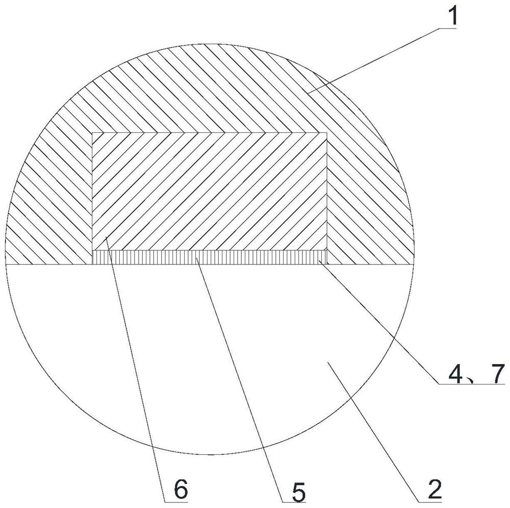
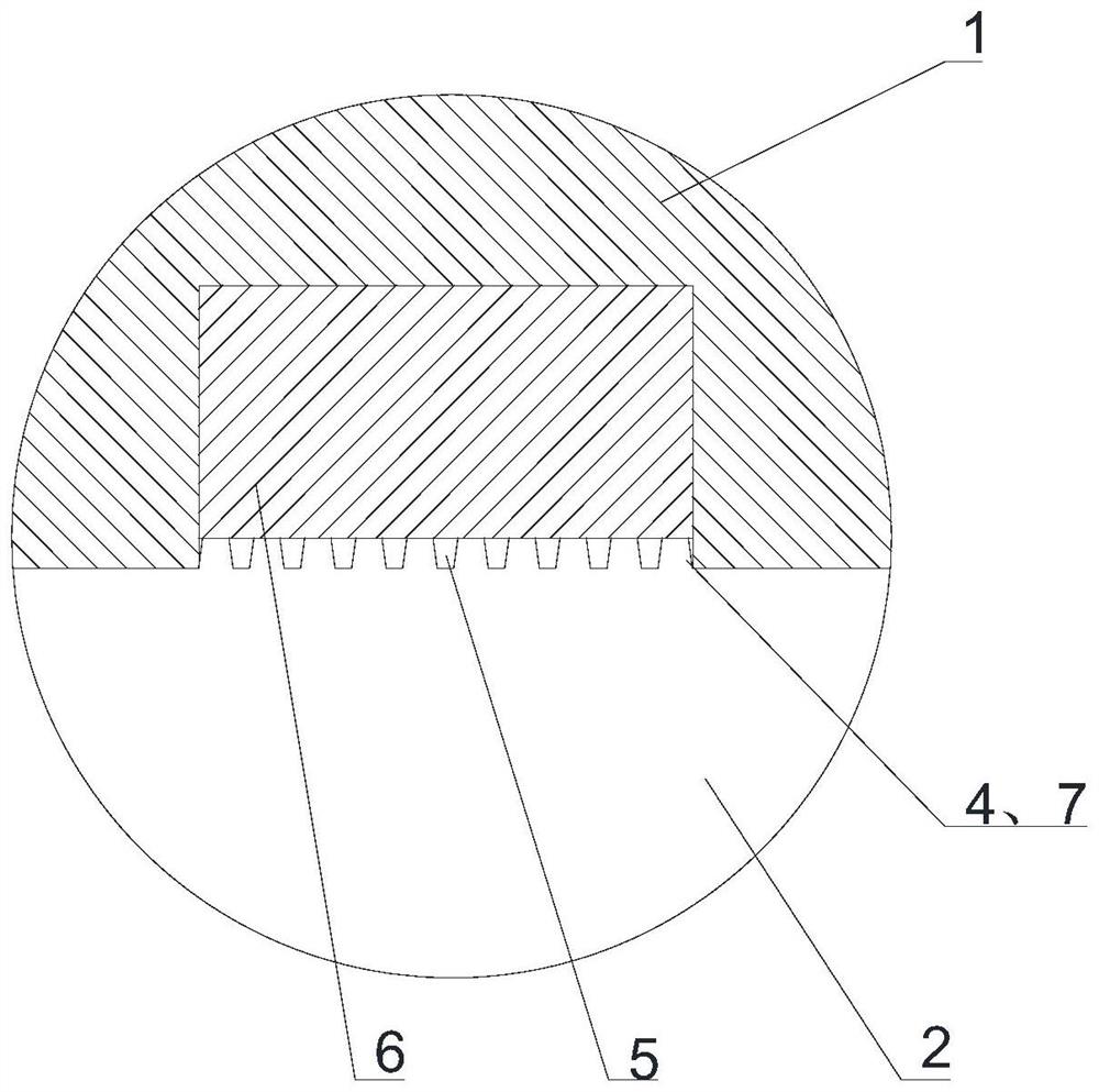
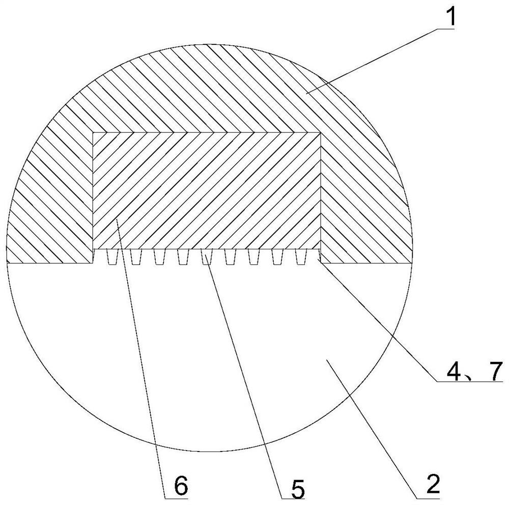
[0031] refer to Image 6 As shown, the embodiment of the present disclosure provides a fluid power device, the fluid power device may be a compressor, an engine, a water pump, an oil pump, etc.; For fluid, a rotatable impeller is installed in the fluid channel 2, and a circle of blades 3 is arranged on the impeller, and the rotation of the blades can drive the fluid from one end of the fluid channel 2 to the other end of the fluid channel;

[0032] However, there is an unavoidable leakage gap between the top of the blade 3 and the side wall of the fluid passage 2; when the fluid power device is working, a gap leakage flow from the pressure surface of the blade 3 to the suction surface will be formed in the gap: this gap Leakage flow will seriously affect the stable operation of fluid power equipment.

[0033] Based on this, an embodiment of the present disclosure provides a casing to break up the gap leakage flow and reduce the impact of the gap leakage flow on the stability ...


PUM


Abstract

The invention discloses a cartridge receiver and fluid power equipment. The cartridge receiver comprises a cartridge receiver body, an impeller with blades can be installed in an overflowing channel, the inner wall surface of the cartridge receiver body is provided with concave parts and convex parts arranged on the bottom surfaces of the concave parts, and the concave parts are continuously or intermittently arranged in the circumferential direction of the cartridge receiver body; multiple convex parts are arranged in each concave part and used for scattering gap leakage flow on the side wall of a fluid channel. According to the cartridge receiver and the fluid power equipment, the gap leakage flow acts with the multiple convex parts in the concave parts, the originally formed gap leakage flow is scattered into smaller fluid groups, and the crushed fluid groups are easily brought to the downstream by the main flow, so that the problems of unsteady oscillation, flow blockage and the like caused by the gap leakage flow are inhibited; and therefore, the blade load of a blade top area generated by gap leakage flow is reduced, and the stable operation margin of the fluid power equipment is expanded; and under the blade top gap of the structure, the original design shape of the side wall of the fluid channel does not need to be changed in a large range, and the problem of gap leakage flow is solved.

Description

technical field [0001] The disclosure belongs to the technical field of fluid power, and in particular relates to a casing and fluid power equipment. Background technique [0002] When the traditional compressor is in use, it may stall. The possible reason is: when the compressor is running, due to the pressure difference between the pressure surface and the suction surface of the blade, the fluid in the area between the blade tip and the inner surface of the casing will From the pressure surface to the suction surface, a gap leakage flow is formed. Especially in the near-stall condition with a small flow rate, this leakage flow will be more complicated, showing unsteady oscillation characteristics, and this leakage flow seriously affects the performance of the compressor. Stable operation. The research shows that the overflow of the leading edge of the gap leakage flow and the backflow of the trailing edge may be the stall mechanism of the compressor, and the axial backwar...

Claims


Application Information

Patent Timeline
IPC IPC(8): F04D29/40F04D29/66
CPCF04D29/403F04D29/667
Inventor 孙大坤王宇晴李佳张晋铭董旭孙晓峰
Owner BEIHANG UNIV
Learn More