Indoor water circulation system

A water circulation and water pump technology, which is applied in the field of building temperature regulation, can solve problems such as reducing the service life and affecting the normal operation of electrical equipment, and achieves the effect of saving electric energy.

Active Publication Date: 2022-01-04
宁波双侨园林建设有限公司
View PDF16 Cites 0 Cited by
  • Summary
  • Abstract
  • Description
  • Claims
  • Application Information

AI Technical Summary

Problems solved by technology

[0005] In view of the related technologies mentioned above, the inventor believes that there is a possibility that sending air with high humidity directly into the factory building may affect the normal operation of the electrical equipment in the factory building and reduce its service life

Method used


Image

  • Indoor water circulation system
  • Indoor water circulation system
  • Indoor water circulation system

Examples


Embodiment 1

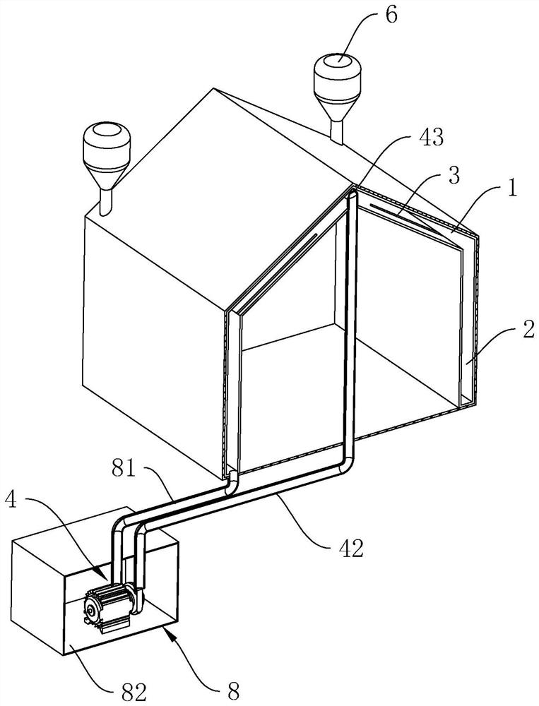
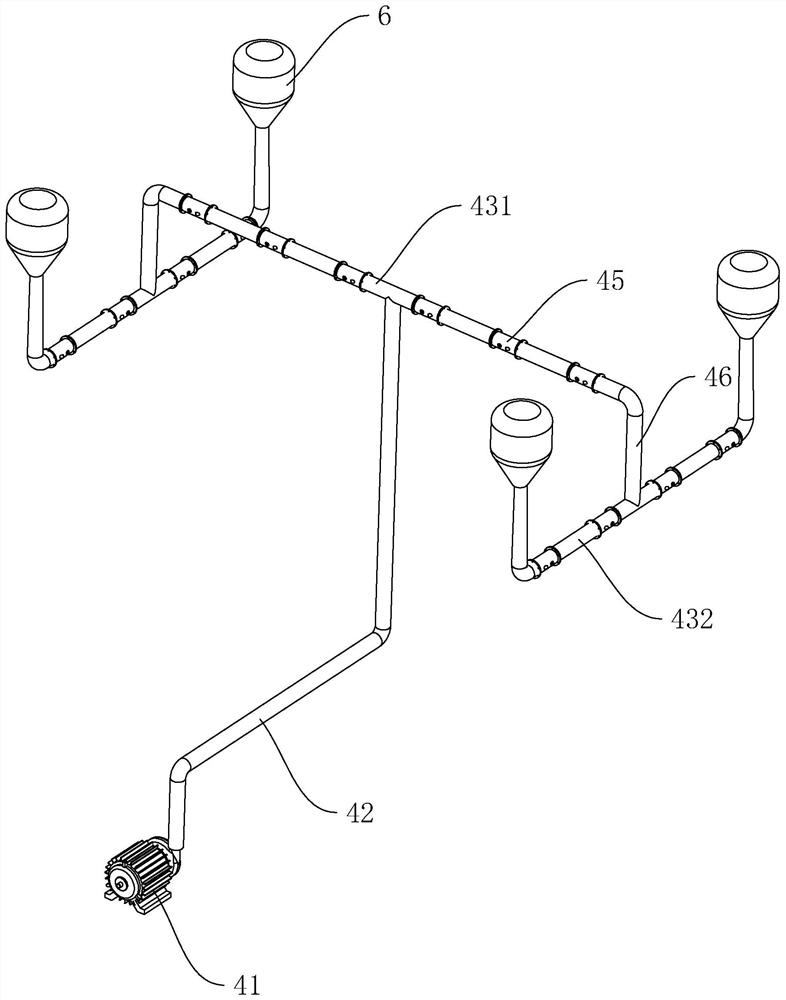
[0038] Embodiment 1, with reference to figure 1 , this embodiment discloses an indoor water circulation system, including a heat insulation layer, a pumping assembly 4 and a recovery assembly 8, the heat insulation layer is used to install the inner room, the heat insulation layer is provided with a cavity for water to flow through, and the pumping The component 4 pumps water flow into the cavity, so that the water flow takes away the heat of the heat insulation layer, and the recovery component 8 can recycle the water to realize water recycling.

[0039] The heat insulation layer includes a roof heat insulation layer 1 and a wall heat insulation layer 2. The roof heat insulation layer 1 is fixedly installed under the roof of the building and is closely attached to the roof; the wall heat insulation layer 2 is arranged on the outer wall of the building and close to the wall, the roof insulation layer 1 and the wall insulation layer 2 jointly surround the indoor space, reducing...

Embodiment 2

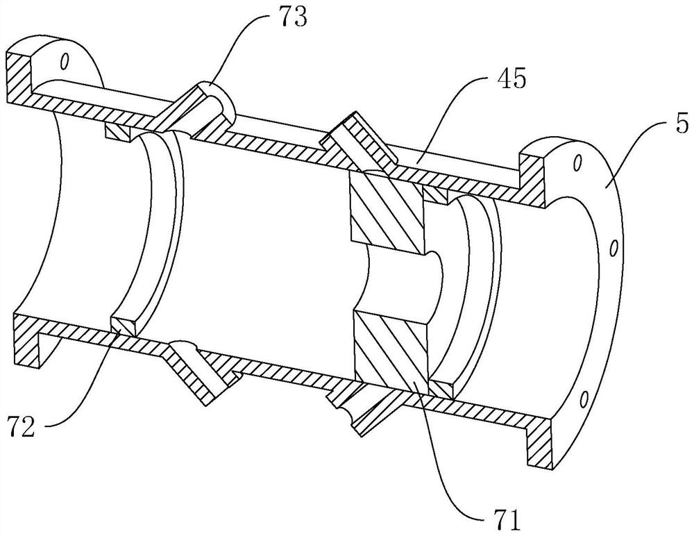
[0049] Embodiment 2, with reference to Figure 4 The difference between this embodiment and Embodiment 1 is that the guide plate 71 is provided with a rotating shaft 74 perpendicular to the drain pipe. Limiting blocks 72 for limiting the travel of the guide plate 71 are respectively provided on both sides of the nozzle.

[0050] The implementation principle of an indoor water circulation system in the embodiment of the present application is as follows: when water flows from the water pump 41 to the energy storage tank 6, the guide plate 71 is impacted by the water flow and rotates to the right until it contacts the limit block 72 on the right, Let the water flow out from the left side of the drain hole along the guide plate 71; similarly, when the water flows from the water storage tank to the drain pipe, the guide plate 71 is impacted by the water flow and rotates to the left until it contacts the stopper 72 on the left side , so that the water flows out from the right side...


PUM


Abstract

The invention relates to an indoor water circulation system, and belongs to the field of building temperature regulation. The indoor water circulation system comprises a heat insulation layer, a pumping assembly, a recycling assembly and an energy storage assembly, wherein the heat insulation layer is arranged on the inner wall of a building, and a cavity is formed in the heat insulation layer; the pumping assembly comprises a water pump and a drainage pipe connected to the water pump, the drainage pipe is located in the cavity of the heat insulation layer, and a plurality of water outlet holes are formed in the drainage pipe in the length direction; the recycling assembly comprises a recycling box and a recycling pipe arranged on the recycling box, and the recycling pipe communicates with the cavity of the heat insulation layer; and the energy storage assembly comprises an energy storage box, and the energy storage box is connected to the end, away from the water pump, of the drainage pipe. The indoor water circulation system has the effect that the humidity in the plant is not increased while the plant is kept at a low temperature.

Description

technical field [0001] The present application relates to the field of building temperature regulation, in particular to an indoor water circulation system. Background technique [0002] In order to obtain a larger span and area, large-scale industrial plants often use steel structure plants. Steel structure plants include steel skeletons and roofs. Steel skeletons are composed of columns, frame beams, roof trusses or roof beams. High-quality steel structures and color steel plates will absorb a lot of heat when the weather is relatively hot, making the temperature in the factory building higher. [0003] At present, industrial plants often use high-power air-conditioning equipment to cool down the plant, but the air-conditioning equipment consumes a lot of power. On the one hand, it consumes a lot of energy, which is not conducive to green production, and on the other hand, the cost of use is relatively high. [0004] The Chinese patent with the publication number CN111878...

Claims


Application Information

Patent Timeline
Patent Type & Authority Applications(China)
IPC IPC(8): F24F5/00F24F13/02
CPCF24F5/0003F24F5/0017F24F5/0089F24F13/02Y02E60/14
Inventor 胡长弟
Owner 宁波双侨园林建设有限公司
Why Eureka
Try Eureka