Stimulated Brillouin scattering microwave frequency measuring device and method based on optical chirp chain

A microwave frequency measurement and optical technology, which is applied in the field of optical measurement, can solve the problems of reducing frequency measurement accuracy, limiting dynamic measurement capability, and reducing measurement speed, etc., and achieves the goal of improving frequency measurement accuracy, shortening measurement time, and high-precision instantaneous frequency measurement Effect

Active Publication Date: 2022-01-04
HARBIN INST OF TECH
View PDF5 Cites 4 Cited by
  • Summary
  • Abstract
  • Description
  • Claims
  • Application Information

AI Technical Summary

Problems solved by technology

However, the existing Brillouin instantaneous frequency measurement technology needs to repeatedly sweep and demodulate the frequency of the signal to be measured, which takes a long time. At the same time, it needs to use electrical means to repeatedly load the intercepted microwave signal fragments into the optical domain, which reduces its measurement speed. , which limits its dynamic measurement capability; in addition, the measurement method of the frequency-amplitude mapping curve reduces the accuracy of frequency measurement

Method used


Image

  • Stimulated Brillouin scattering microwave frequency measuring device and method based on optical chirp chain
  • Stimulated Brillouin scattering microwave frequency measuring device and method based on optical chirp chain
  • Stimulated Brillouin scattering microwave frequency measuring device and method based on optical chirp chain

Examples


Embodiment Construction

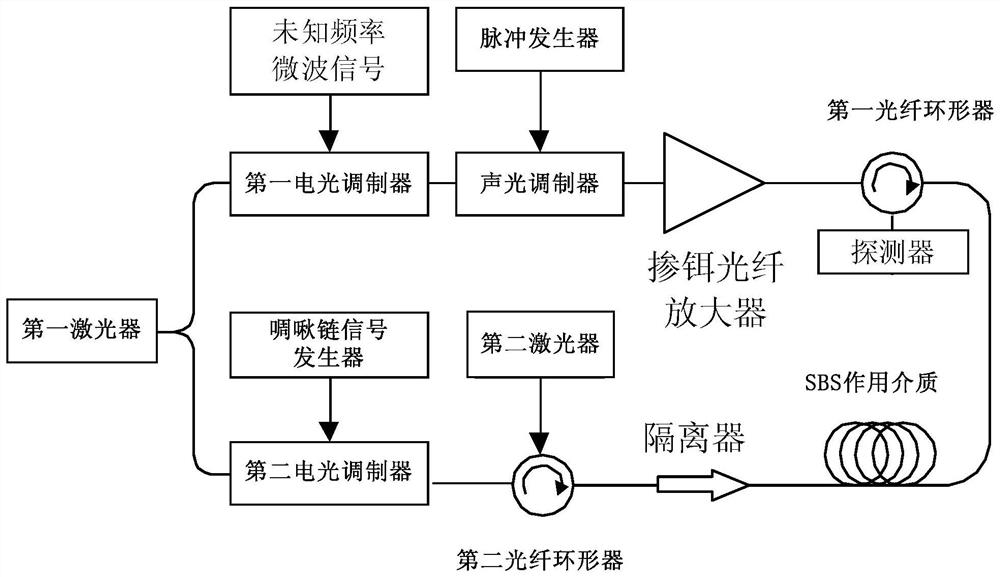
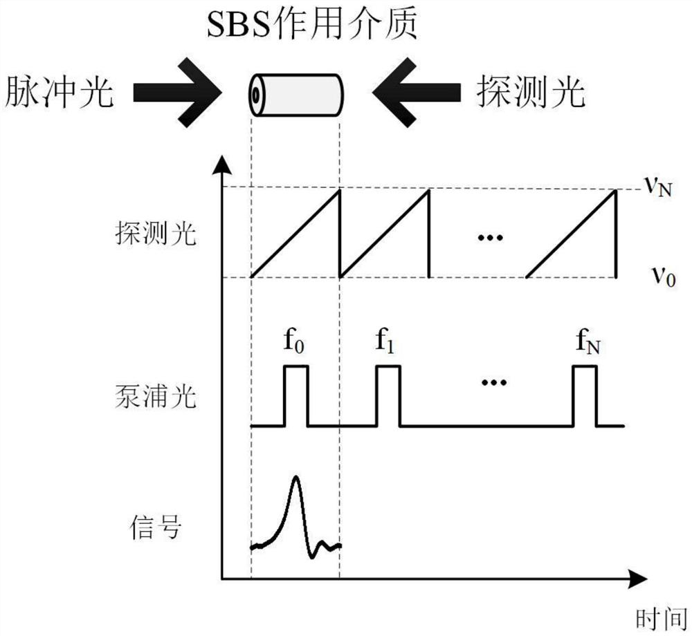
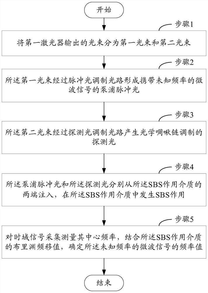
[0043] Exemplary embodiments of the present invention will be described below with reference to the accompanying drawings. In the interest of clarity and conciseness, not all features of an actual implementation are described in this specification. It should be understood, however, that in developing any such practical embodiment, many implementation-specific decisions must be made in order to achieve the developer's specific goals, such as meeting those constraints related to the system and business, and those Restrictions may vary from implementation to implementation. Furthermore, it should be understood that development work, while potentially complex and time-consuming, would nevertheless be a routine undertaking for those skilled in the art having the benefit of the teachings herein.

[0044] Here, it should also be noted that, in order to avoid obscuring the present invention due to unnecessary details, only the device structure and / or processing steps closely related ...


PUM


Abstract

The invention provides a stimulated Brillouin scattering microwave frequency measuring device and method based on an optical chirp chain. The device comprises a first laser, a coupler, a pulsed light modulation light path, a probe light modulation light path, an SBS acting medium and a detector; wherein a light beam output by the first laser is divided into a first light beam and a second light beam through the coupler; the first light beam passes through the pulse light modulation light path to form pump pulse light carrying a microwave signal with a to-be-measured frequency; the second light beam passes through the probe light modulation light path to generate probe light modulated by an optical chirp chain; the pump pulse light and the probe light are injected from the two ends of the SBS acting medium respectively, and an SBS action occurs in the SBS acting medium; and the detector collects the time domain signal, measures the center frequency of the time domain signal, and determines the frequency value of the microwave signal with the frequency to be measured in combination with the Brillouin frequency shift value of the SBS acting medium. By means of the invention, the high-precision single-signal instantaneous frequency measurement is realized.

Description

technical field [0001] The invention belongs to the field of optical measurement, and in particular relates to a stimulated Brillouin scattering microwave frequency measurement device and method based on an optical chirp chain. Background technique [0002] Instantaneous frequency measurement is a technology used to detect the frequency of microwave signals. It has the advantages of wide bandwidth, high speed, and high flexibility. It has been widely used in wireless communication and electronic warfare and other fields. In electronic warfare, intercepting enemy radar signals in time and quickly and accurately identifying the working frequency band and modulation characteristics of enemy radar before the signal confrontation between the enemy and the enemy will help us gain the upper hand. Therefore, timely, fast and accurate estimation of microwave signal frequency is critical for defense, radar warning and electronic intelligence. [0003] The microwave photonics instanta...

Claims


Application Information

Patent Timeline
Patent Type & Authority Applications(China)
IPC IPC(8): H04B10/079H04B10/524H04B10/69G01R23/02
CPCH04B10/0795H04B10/524H04B10/691G01R23/02
Inventor 董永康王赫楠巴德欣
Owner HARBIN INST OF TECH
Why Eureka
Try Eureka