
Composite material thin shell plane folding and unfolding device and folding and unfolding method

A composite material and thin shell technology, applied in the field of mechanical structure, can solve the problems of heavy weight, complex structure, and many parts, etc., and achieve the effects of high space utilization, simple structure, and large specific strength and specific modulus.

Pending Publication Date: 2022-01-07
FUZHOU UNIVERSITY
View PDF6 Cites 0 Cited by
  • Summary
  • Abstract
  • Description
  • Claims
  • Application Information

AI Technical Summary

Problems solved by technology

The traditional solution is to divide it into several small-area plates or frames, and complete the deformation through mechanical assembly or folding. These structures are often more complicated, have more parts, are heavier and difficult to achieve repeated folding and unfolding

Method used


Image

  • Composite material thin shell plane folding and unfolding device and folding and unfolding method
  • Composite material thin shell plane folding and unfolding device and folding and unfolding method
  • Composite material thin shell plane folding and unfolding device and folding and unfolding method

Examples


Embodiment Construction

[0030] The following will clearly and completely describe the technical solutions in the embodiments of the present invention with reference to the drawings in the embodiments of the present invention.

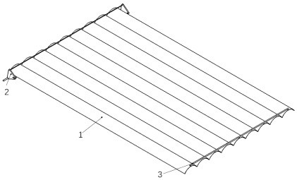
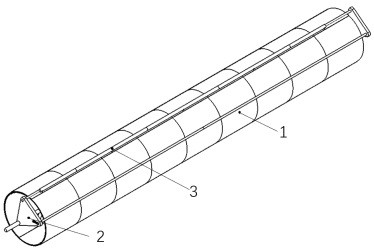
[0031] Such as Figure 1-8 As shown, a plane folding device for a thin composite shell includes a thin composite shell 1, a folding mechanism 2, and an end support arm 3. The folding mechanism is installed on one side of the composite shell, and the end support arm is installed on the composite On the opposite side of the installation position of the material thin shell folding mechanism;

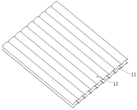
[0032] The composite material thin shell includes a structural layer 11 and a connecting layer 12. The structural layer is composed of at least two arc bistable composite material tape structures juxtaposed. The connecting layer is a flexible film or fabric bonded on one side or both sides of the structural layer. side surface, and connect the structural layers into a whole; by adjusting t...


PUM


Abstract

The invention relates to a composite material thin shell plane folding and unfolding device and folding and unfolding method. The composite material thin shell plane folding and unfolding device comprises a composite material thin shell, a folding and unfolding mechanism and a tail end supporting arm, wherein the folding and unfolding mechanism is mounted on one side edge of the composite material thin shell, and the tail end supporting arm is mounted on the opposite side edge of the mounting position of the composite material thin shell folding and unfolding mechanism. The composite material thin shell comprises a structural layer and a connecting layer; the structural layer is composed of at least two sections of arc bistable composite material tape structures which are arranged in parallel; and the connecting layer is a flexible film or fabric which is bonded on the surface of one side or two sides of the structural layer. The folding and unfolding mechanism comprises side plates, a head end supporting arm, a first limiting rod and a second limiting rod. The tail end supporting arm is formed by sequentially connecting at least two sections of outer telescopic rods, and the outer telescopic rods are installed on the convex face fixed to the tail end of the composite material thin shell. The device can be kept stable in an unfolded state and a folded state, can be repeatedly folded and unfolded, is high in space utilization rate, simple in structure, large in specific strength and specific modulus, resistant to high temperature and corrosion and capable of adapting to complex and changeable working environments.

Description

technical field [0001] The invention relates to the technical field of mechanical structures, in particular to a plane folding device and a method for thin composite material shells. Background technique [0002] Some movable large-scale equipment / devices need to use a large-area flat panel or frame structure (such as the substrate of a solar wing, the backplane of a large display). In order to facilitate transportation, these board or frame structures meet the strength requirements while being lightweight and easily foldable. The traditional solution is to divide it into several small-area plates or frames, and complete the deformation through mechanical assembly or folding. These structures are often complicated, have many parts, are heavy and difficult to achieve repeated folding and unfolding. Contents of the invention [0003] The object of the present invention is to address the above deficiencies and to provide a thin composite material shell plane folding device a...

Claims


Application Information

Patent Timeline
IPC IPC(8): B32B3/16B32B27/38B32B27/36B32B27/32B32B27/20B32B1/00B32B3/28B32B27/12B32B27/08B32B27/34B32B5/02B32B27/06
CPCB32B3/16B32B27/38B32B27/36B32B27/32B32B27/20B32B1/00B32B3/28B32B27/12B32B27/08B32B27/34B32B5/02B32B2262/101B32B2262/0253B32B2262/08B32B2262/065B32B2262/106
Inventor 王冰杨潮钟舜聪
Owner FUZHOU UNIVERSITY
Learn More