Blowout preventer unit for workover rig

A blowout preventer and workover rig technology, used in wellbore/well components, earthmoving, sealing/packing, etc., can solve the problems of limited use times, long-term shut-in use is not allowed, and achieve good sealing effect , to ensure the effect of strength

Inactive Publication Date: 2022-01-07
山东旭能石油装备有限责任公司
View PDF1 Cites 1 Cited by
  • Summary
  • Abstract
  • Description
  • Claims
  • Application Information

AI Technical Summary

Problems solved by technology

[0004] In the prior art, in the blowout preventer group, through the combined use of the ram blowout preventer and the annular blowout preventer, the annular blowout preventer can completely seal the wellhead of the oil well, and is the last barrier for the blowout at the wellhead. However, the interior of the existing annular blowout preventer is sealed by the deformation of the elastic annular rubber core, the number of times of use is limited, and it is not allowed to shut down the well for a long time

Method used


Image

  • Blowout preventer unit for workover rig
  • Blowout preventer unit for workover rig
  • Blowout preventer unit for workover rig

Examples


Embodiment 1

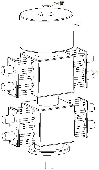
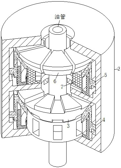
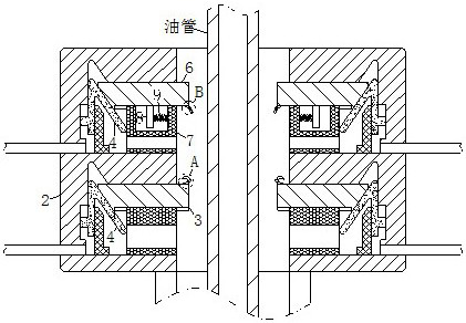
[0032] Such as Figure 1 to Figure 3 As shown, a blowout preventer group for a workover rig according to an embodiment of the present invention includes a ram blowout preventer body 1, an annular blowout preventer housing 2 and an annular rubber core 3; the ram blowout preventer The top of the body 1 is fixedly connected with an annular blowout preventer casing 2, and the annular blowout preventer casing 2 is designed in a ring structure; the inside of the annular blowout preventer casing 2 is provided with a first sealing groove; the first The inside of the sealing groove is slidingly connected with the first piston 4; the top position of the first piston 4 is provided with an annular rubber core 3; Two sealing grooves; the inside of the second sealing groove is slidably connected with the second piston 5; the inside of the second sealing groove is slidably connected with the sealing block 6 at the top position of the second piston 5, and the sealing block 6 is uniform along ...

Embodiment 2

[0040] Such as Figure 8 As shown in Comparative Example 1, another embodiment of the present invention is: one of the gaskets 16 has a connection groove on its surface, and the cross section of the connection groove is designed as a spherical structure; The surface of the sealing gasket 16 is fixedly connected with the connecting plate 21 relative to the position of the connecting groove, and the volume of the connecting groove is greater than the volume of the connecting plate 21; during work, by setting the connecting plate 21, when the two sealing gaskets 16 move relatively, a The connection plate 21 on the surface of the gasket 16 on one side will be inserted into the connection groove on the surface of the gasket 16 on the other side. Since the gasket 16 is designed with elastic material, the mouth of the connection groove is in a sealed state in the initial state. The elastic deformation automatically opens, ensuring that a large amount of foreign matter will not be int...


PUM


Abstract

The invention belongs to the field of oil exploitation, and particularly relates to a blowout preventer unit for a workover rig. The blowout preventer unit comprises a ram preventer body, an annular blowout preventer shell and an annular rubber core. The annular blowout preventer shell is fixedly connected to the top of the ram preventer body. The annular rubber core and a sealing block are arranged in the annular blowout preventer shell, and the sealing block is located at the top of the annular rubber core. A first piston is arranged at the bottom of the annular rubber core. A second piston is arranged at the bottom of the sealing block. According to the blowout preventer unit, the annular rubber core is reserved and can achieve the sealing and shielding effects, and blowout objects are basically prevented from being continuously guided into the position of the sealing block; when the blowout state is stopped, the sealing block is controlled to conduct sealing, and the situation that a large number of foreign matter is clamped into the sealing face position of the sealing block, and the sealing effect is influenced is avoided; and sealing is conducted through the hard sealing block, the strength of a sealing structure is guaranteed, and therefore the continuous sealing effect can be achieved.

Description

technical field [0001] The invention belongs to the field of petroleum exploitation, in particular to a blowout preventer group for a workover rig. Background technique [0002] The blowout preventer is used to close the wellhead during oil testing, workover, and completion to prevent blowout accidents. It is a safety sealing wellhead device commonly used in oil fields to prevent blowout. It is usually a large gate equipped with a ram type blowout preventer. During operation, a sealed annular space will be formed between the pipe string and the wellbore, and the well sealing can also be completed independently when there is a pipe string in the well. [0003] A Chinese patent with the application number CN113250640A discloses a ring-shaped blowout preventer. The bottom of the casing is movably installed with a rotating sleeve, and the inside of the casing is movably installed on the top of the support cylinder. The inside of the casing is located on the outer ring of the sup...

Claims


Application Information

Patent Timeline
Patent Type & Authority Applications(China)
IPC IPC(8): E21B33/06
CPCE21B33/06
Inventor 王西武刘磊王茂华颜琪成涛张晨欧阳新良
Owner 山东旭能石油装备有限责任公司
Why Eureka
Try Eureka