Standing wave azimuth angle measurement method based on asymmetric parameter identification of hemispherical resonator gyroscope detection path

A hemispherical resonant gyro and asymmetric technology, applied in the inertial field, can solve the problems of X/Y detection signal phase difference, X/Y detection electrode non-orthogonal, X/Y detection signal gain inconsistency, etc., to improve measurement accuracy Effect

Active Publication Date: 2022-01-07
HARBIN INST OF TECH
View PDF12 Cites 7 Cited by
  • Summary
  • Abstract
  • Description
  • Claims
  • Application Information

AI Technical Summary

Problems solved by technology

[0003] The purpose of the present invention is to solve the problem that there is a measurement error in the standing wave azimuth due to the inconsistency of the gain of the X/Y detection signal, the non-orthogonality of the X/Y

Method used


Image

  • Standing wave azimuth angle measurement method based on asymmetric parameter identification of hemispherical resonator gyroscope detection path
  • Standing wave azimuth angle measurement method based on asymmetric parameter identification of hemispherical resonator gyroscope detection path
  • Standing wave azimuth angle measurement method based on asymmetric parameter identification of hemispherical resonator gyroscope detection path

Examples


specific Embodiment approach 1

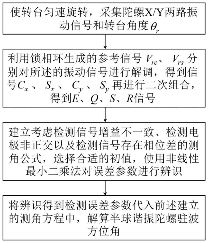
[0056] Specific implementation mode 1. Combination figure 1This embodiment will be described. A standing wave azimuth measurement method based on asymmetric parameter identification of a hemispherical resonator gyro detection channel described in this embodiment, the method specifically includes the following steps:

[0057] Step 1. Make the turntable rotate at a constant speed, and collect the two vibration signals of the hemispherical resonant gyroscope X and Y and the angle θ of the turntable r ;

[0058] Step 2, demodulating the collected X and Y vibration signals to obtain demodulated signals; and combining the demodulated signals to obtain combined signals E, Q, S and R;

[0059] Step 3, establishing an angle measurement formula that considers the gain inconsistency of the two vibration signals of X and Y, the non-orthogonal detection electrodes of X and Y, and the phase difference between the two vibration signals of X and Y;

[0060] Establish an angle measurement f...

specific Embodiment approach 2

[0065] Specific embodiment 2. The difference between this embodiment and specific embodiment 1 is that the two vibration signals of X and Y are:

[0066] In the case of detection path asymmetry error, the expression of the acquisition signal is:

[0067]

[0068] Among them, x represents the vibration signal of the X channel, y represents the vibration signal of the Y channel, and k x Represents the electrode gain of X channel, k y Represents the electrode gain of the Y channel, h 1 Represents the initial phase of the X-way vibration signal, h 2 Represents the initial phase of the Y-way vibration signal, ω is the vibration frequency of the harmonic oscillator, t is time, θ represents the angle between the antinode axis of the main wave and the X axis, a represents the antinode of the main wave, q represents the antinode of the orthogonal wave, h 2 Represents the initial phase of the vibration signal of channel Y.

[0069] The X-axis and the Y-axis in this embodiment are...

specific Embodiment approach 3

[0071] Specific implementation mode three, the difference between this implementation mode and specific implementation mode one or two is: the described pair of X, Y two-way vibration signal that collects is demodulated, and its specific process is:

[0072] Step 21, using a phase-locked loop to generate a reference signal V rc , V rs ;

[0073] V rc =2cos(ωt+h)

[0074] V rs =2sin(ωt+h)

[0075] Among them, h represents the initial phase of the reference signal;

[0076] Step 22, using the generated reference signal to demodulate the two vibration signals of X and Y;

[0077]

[0078] Among them, C x , S x 、C y and S y is the demodulated signal, β 1 and beta 2 represents an intermediate variable.

[0079] Other steps and parameters are the same as those in Embodiment 1 or Embodiment 2.


PUM


Abstract

The invention discloses a standing wave azimuth angle measurement method based on asymmetric parameter identification of a hemispherical resonator gyroscope detection path, and belongs to the technical field of inertia. According to the invention, the problem of measurement error of a standing wave azimuth angle caused by inconsistent gains of X/Y detection signals, non-orthogonal X/Y detection electrodes and phase difference of the X/Y detection signals is solved. An improved angle measurement equation is established based on the gain ratio, the detection electrode deflection angle and the phase difference, error parameters are identified by using a nonlinear least square method or an extended Kalman filtering method, so that the accurate azimuth angle of the harmonic oscillator standing wave is calculated, the problem of inaccurate angle measurement caused by detection errors is solved, and the measurement precision of the hemispherical resonator gyroscope is improved. The method can be applied to the technical field of inertia.

Description

technical field [0001] The invention belongs to the technical field of inertia, and in particular relates to a standing wave azimuth measurement method based on asymmetric parameter identification of a hemispherical resonant gyro detection channel. Background technique [0002] Hemispherical resonant gyroscope is a mainstream high-precision inertial device widely used in aviation, aerospace, navigation and other fields. When there is an external angle input, the standing wave of resonator vibration will precess due to the Coriolis force, and the standing wave azimuth The angle is proportional to the input angle. The standing wave position is detected in real time through the X / Y two-way signal, and the external input angle and angular velocity can be measured. Due to the mismatch of the parameters of the two detection circuits, the influence of environmental factors such as manufacturing errors, assembly errors, and temperature on the circuit parameters, the gains of the X / ...

Claims


Application Information

Patent Timeline
IPC IPC(8): G01C21/16G01C21/18G01C21/20
CPCG01C21/16G01C21/18G01C21/20
Inventor 解伟男王奇奚伯齐孙一为伊国兴王常虹
Owner HARBIN INST OF TECH
Why Eureka
Try Eureka