Control method of dust suppression vehicle and dust suppression vehicle

A control method and controller technology, applied in the direction of program control, separation method, computer control, etc., can solve the problem that the output power cannot be automatically allocated to fans and water pumps.

Pending Publication Date: 2022-01-07
FUJIAN LONGMA ENVIRONMENTAL SANITATION EQUIP
7 Cites 0 Cited by

AI-Extracted Technical Summary

Problems solved by technology

[0012] For this reason, it is necessary to provide a control method of a dust suppression vehicle and the dust suppression vehicle, which are used to solve the problem that in the prior art, it is impossible to realize that a dust suppression vehicle with an alternator unit is equipped wi...

Method used

In this way, the controller 10 is electrically connected to the fan module 1 and the high-pressure water pump module 11 respectively, and the CAN module 4 is connected to the chassis 5, the generator set assembly 3, the controller 10, and the low-pressure waterway module 7 respectively; cancel the AC frequency conversion In the way of replacing the controller with the controller 10, the parameters of the generator set assembly 3 can be collected through the CAN module 4, and the engine speed in the generator set can be controlled according to the speed demand of the fan module 1 or the high-pressure water pump module 11, and the engine can be adjusted and increased. Accelerator and air intake realize intelligent adjustment and control of fan speed and water pump sprinkling. Only one controller 10 is needed to control the fan and the water pump at the same time, the cost is greatly reduced, and the intelligent control of the generator set and the reasonable power distribution of the controller 10 are effectively realized.
In this way, the three-phase electricity is received by the controller 10, and the three-phase electricity is rectif...

Abstract

The invention relates to a control method of a dust suppression vehicle and a dust suppression vehicle. The control method comprises the following steps that: a generator set assembly is started; and when a draught fan module or a high-pressure water pump module is started, a CAN module collects parameters of the generator set assembly, a control message is sent to the generator set according to the rotating speed requirement of the draught fan module or the high-pressure water pump module, the rotating speed of an engine in the generator set is increased, the output power of the generator set is increased, generating capacity can be improved, a phase angle is automatically matched, the voltage is stabilized at 380V, the output power is subjected to one-time distribution and output, and the CAN module provides a loading starting instruction for a controller through the control message. The control method is different from the prior art in that only one controller is needed to control a fan and a water pump at the same time, so that the cost is greatly reduced, and reasonable power distribution of the intelligent control generator set and the controller is effectively achieved.

Application Domain

Programme controlComputer control +3

Technology Topic

Automotive engineeringGenerating capacity +4

Image

  • Control method of dust suppression vehicle and dust suppression vehicle
  • Control method of dust suppression vehicle and dust suppression vehicle
  • Control method of dust suppression vehicle and dust suppression vehicle

Examples

  • Experimental program(1)

Example Embodiment

[0067] In order to explain the technical content, constructive features, the purpose and effects of the technical solution, the following combination of the specific embodiments will be described with reference to the accompanying drawings.
[0068] In the description of the present application, the term "first", "second", only for the purpose of the description unless otherwise specified and defined, unless otherwise specified or implied; unless otherwise specified or Note, the term "multiple" refers to two or more; the term "connection", "fixed", etc. Connect, or electrically connected; may be directly connected, or indirectly over the intermediate medium. The specific meaning of the above terms in the present invention can be understood in terms of specific cases.
[0069] In the description of this specification, it is to be understood that "upper", "lower", "left", "right" oriented orientation described in the present application will be described by the angle shown in the drawings, not It should be understood to be limited to the embodiment of the present application. Further, in the context, it is also a need to understand that when a component is connected to another component "on" or "under", it can not only be directly connected to another element "on" or "down", or Indirect connection through the intermediate element in another component "" "or" under ".
[0070] The prior art cannot realize that only one controller is equipped with a controller to control the fan and water pump, and the prior art cannot automatically allocate output power to the fan and water pump, realize wind speed, water pump sprinkler Intelligent adjustment control.
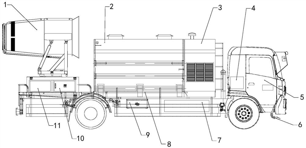
[0071] See Figure 1 to 5 In this embodiment, the present embodiment relates to a dust collector, the dust collector includes a chassis 5, a generator set assembly 3, a CAN module 4, a controller 10, a fan module 1, a high pressure water pump module 11, a low pressure water circuit module 7, a sprinkle pipe module 6 The can body assembly 2 and the operation panel, the fan module 1 is disposed at the rear end of the chassis 5, the sprinkler module 6 is disposed at the front end of the chassis 5, the can body assembly 2 is supplied by the high pressure water pump module 11 for the fan module 1 water, can body The total 25 is water supply through the low pressure water path module 7 for the water supply pipeline module 6, in this embodiment, the operation panel includes a power switch, a screen, alarm light, a dust removal button, a sprinkler button, a parallel button, and the like, and the tank assembly 2 is provided. Water level sensor, water level sensor is electrically connected to the CAN module 4.
[0072] The generator set assembly 3 is electrically connected to the fan module 1, and the power generator set 3 is electrically connected to the fan module 1, and the generator set assembly 3 is electrically connected. The CAN module 4 is respectively connected to the chassis 5, the generator set assembly 3, control The device 10, the low voltage waterway module 7 communication connection.
[0073] In this embodiment, the generator set assembly 3 is electrically connected to the fan module 1, the high pressure water pump module 11, and the low pressure water path module 7 via the high voltage line module 8, respectively.
[0074] The generator set assembly 3 is used to power the fan module 1, the high pressure water pump module 11, the low pressure water path module 7, and the chassis 5 provides power by the strobe for the sprinkler block module 6; the CAN module 4 is separately related to the operation panel, the generator set 3, respectively. The chassis 5 communication connection; wherein the controller 10 includes a rectifier module, a precharge module, a first inverter unit, and a second inverter unit, a rectifier module and a precharge module, and the precharge module is respectively associated with the first inverter unit, respectively. The second inverter unit is electrically connected, the first inverter unit, and the second inverter unit are electrically connected to the fan module 1, the high pressure water pump module 11, respectively.
[0075] In this embodiment, the controller 10 controls the integral sealing of the finishing structure, and the insertion head is used to use the waterproof grade IP68, and the internal pressure line beam joint is saved in the interior with respect to the multi-controller 10 type. A rectifier and inverter reach the use effect, and effectively adapt a variety of three-phase voltage platform.
[0076] As such, the three-phase electricity is received by the controller 10, and the three-phase electricity is rectified by the rectifying module of the controller 10, and the bus voltage fluctuates via the support capacitance and the power generation resistance in the pre-charged module, and then output by the inverter unit Sinusoidal three - phase electric to the water pump motor and fan motor for secondary power distribution. Only one controller 10 does simultaneously control the fan and water pump, to achieve an economical and multi-expanded controller 10 shaped dust drum, effectively achieve intelligent control generator set and controller 10 reasonable power distribution, Get the effect of fueling oil.
[0077] In some embodiments, the dust collector also includes a main electrical input interface 9, and the mains input interface 9 is electrically connected to the fan module 1 and the high pressure water pump module 11 via the controller 10, respectively. In this way, through the market power input interface 9, it can be adapted to the municipal power grid and easy to use.
[0078] In the present embodiment, due to the overall CAN module 4, it can be used with intelligent control development such as remote operation and remote monitoring, and the remote platform can be transmitted to the CAN module 4 according to the current water level sensor feedback signal. According to the current water level, the stepped indication is performed according to the current water level. And through a remote communication system, you can inform the driver to get the new water point recently. The enumeration environment can be installed in real time to monitor the current regional pollution environment, and transfer environmental parameters to the cloud platform through the CAN module 4 to provide the optimal spray scheme by large data analysis.
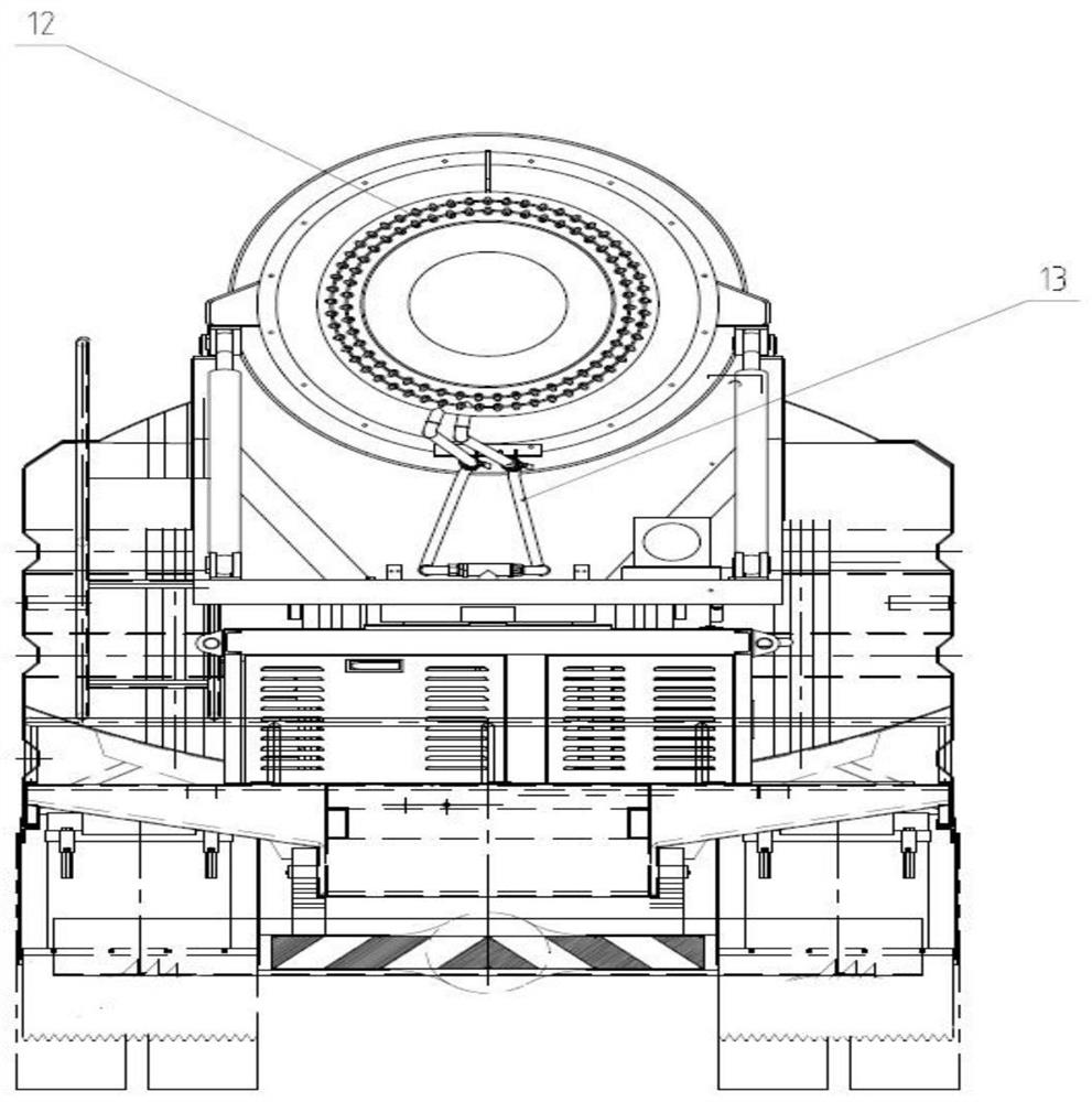
[0079] like Figures 2 to 5 As shown, the fan module 1 includes a wind cylindrical head 12 and a wind cylindrical high pressure water path 13, and the wind tube head 12 is in communication with the tank assembly 2 through the wind cylindrical high pressure water passage 13, and the wind tube head 12 is used to spray, atomize. The fan module 1 also includes a blade 21, a housing 22, an elastic coupling 23, a synchronizing motor 24, and a motor cooling inlet and outlet port 25, and the synchronous motor 24 is transmitted through the elastic coupling 23 and the blade 21, the elastic coupling 23 A flexible connection is provided to prevent the dust drum from moving in the movement, damaging the spindle of the synchronous motor 24. The bearing base 22 is used to support the spindle of the synchronous motor 24, and the motor cooling inlet 55 is used to pass through the coolant, thereby dissipating the synchronous motor 24.
[0080] In this embodiment, the generator set assembly 3 is electrically connected to the controller 10, the water pump of the low pressure water path module 7, respectively, by the high voltage line module 8, and the controller 10 is electrically connected to the fan module 1, the high pressure water pump module 11, respectively, with the high voltage line module 8, respectively. . The operation panel communicates with the CAN module 4, the CAN module 4 communicates with the generator set 3 via CAN 2.0B, and the bus device uses the CAN 2.0B, the CAN module 4 communicates with the ECM processor of the chassis 5. The generator set assembly 3 is connected to the controller 10, the water pump of the low pressure water path module 7, respectively.
[0081] In the present embodiment, the driver issues an instruction to the whole vehicle through the CAN module 4, and when the CAN module 4 receives the instruction, the power generation power and the generator set assembly 3 are matched according to the output of the controller 10, and the controller 10 and the low pressure Module 7 performs instruction transmission to control.
[0082]In this embodiment, the fan module 1 mainly acts as an output high-speed winding, and the water mist is injected, and the power generator set assembly 3 provides power, passed through the high voltage harness module to the controller 10, and the internal rectifier inverse changes by the controller 10 After delivery to the fan module 1.
[0083] The high pressure water pump module 11 mainly acts as an output high pressure water, and the generator set assembly 3 provides power, and is delivered to the controller 10 through the high voltage harness module, and the internal rectifier is rectified by the controller 10, and then transported to the high pressure water pump module 11 power, Then, the tank assembly 2 is transported to the wind cylindrical head 12 by the air cylindrical high pressure water path 13, and the high pressure water atomization is output by the wind cylindrical water atomization process by the wind cylindrical water atomization. Wind beam is shot.
[0084] The low pressure waterway module 7 mainly acts as the output spraying low pressure, and the strip 5 strokes are transferred to the low pressure water path module 7, and then sprayed by the low pressure waterway system through the sprinkler pipeline module 6. The low pressure waterway module 7 can be replaced with the generator set assembly 3 to take electricity, and the sprinkler module 6 is sprayed by the synchronous motor 24 by selecting a low pressure synchronous motor 24.
[0085] This embodiment also relates to a control method of a dust collector, including a chassis 5, a generator set assembly 3, a CAN module 4, a controller 10, a fan module 1, a high pressure water pump module 11, a low pressure water circuit module 7, a power generation The unit assembly 3 is electrically connected to the fan module 1, the high pressure water pump module 11 via the controller 10, and the generator set assembly 3 is electrically connected, and the CAN module 4 is respectively connected to the chassis 5, the generator set assembly 3, the controller. 10, low voltage waterway module 7 communication connection;
[0086] The control method of the dust drum includes the following steps:
[0087] Start the generator set assembly 3, after the startup is started, the parameters of the generator set assembly 3 through the CAN module 4, if there is no fault, then start the generator set, precharge the upper platform;
[0088] When the fan module 1 or the high pressure pump module 11 is activated, the CAN module 4 collects the parameters of the generator set assembly 3, and transmits control packets to the generator set according to the speed of the fan module 1 or the high pressure water pump module 11, the engine in the generator set. Increase the speed, increase the output power of the generator set to increase the power generation, and automatically match the phase angle, stabilize the voltage at 380V, and the output power is allocated, and the CAN module 4 will make the controller 10 proposed to the controller 10 to start the instruction. And use the output power supplied by the generator set to the fan module 1 or the high pressure water pump module 11;
[0089] When the speed demand of the fan module 1 or the high-pressure water pump module 11 is increased, the CAN module 4 transmits an instruction to the controller 10, improves the speed signal, and the controller 10 transmits the demand power back to the CAN module 4, and the CAN module 4 is controlled by calculation. Manager 10 and generator set assembly 3 send instructions;
[0090] When the wind turbine module 1 or the high-pressure water pump module 11 is lowered, the CAN module 4 transmits an instruction to the controller 10, lowers the speed signal, and the controller 10 reduces the demand power, and the power generation unit assembly 3 simultaneously performs power reduction, reducing power distribution. Comparison, the voltage is stable at 380V.
[0091] As such, the controller 10 is electrically connected to the fan module 1, the high pressure water pump module 11, respectively, the CAN module 4 communicates with the chassis 5, the generator set assembly 3, the controller 10, the low pressure water path module 7; the cancel AC drive is replaced In the manner of controller 10, the parameters of the generator set assembly 3 can be acquired by the CAN module 4. According to the speed requirements of the fan module 1 or the high pressure water pump module 11, the rotational speed of the engine in the generator set is controlled, and the engine is adjusted to increase the throttle and into the engine. The gas volume achieves the wind speed of the fan, the intelligent adjustment control of the water pump sprinkler. It is only necessary to control the fan and water pump simultaneously, the cost is greatly reduced, and the intelligent control generator set and the controller 10 are effectively distributed.
[0092] In some embodiments, the power switch is started before starting the generator set assembly 3 step, the screen output prompts whether there is alarm and fault, and collects the packets of the controller 10, check the fan module 1 or high pressure water pump module 11 Is there a launch failure. As such, before starting the generator set assembly 3, it is possible to detect the inside of the dust drum, the fan module 1, and the high pressure pump module 11 fault, and then turn on the generator set assembly 3, and reduce the fault rate.
[0093] In some embodiments, the parameters of the generator set assembly 3 include voltage, rotational speed, intake amount, power distribution ratio, load rate, and alarm signal. As such, the parameters of the generator set assembly 3 can be detected by the CAN module 4, the engine speed, intake amount, power distribution ratio, load rate, and the alarm signal are detected, and it is convenient for the use of subsequent devices.
[0094] In some embodiments, in the step of the secondary assignment of the output power provided by the generator set, by obtaining the target speed requirements of the fan module 1 or the high-pressure water pump module 11, the target torque requirement, and the nominal voltage of the rated voltage is calculated by the formula. Each of the required power, the total power is calculated by the CAN module 4. In this way, the target torque demand and rated voltage can be obtained by obtaining the target speed requirements of the fan module 1 or the high pressure water pump module 11.
[0095] In some embodiments, after the CAN module 4 transmits an instruction to the controller 10 and the generator set assembly 3, when the generator set 3 receives the instruction, improve the speed of the engine, improve the power distribution ratio The rate is stabilized at 380 V, and when the output power of the generator set 3 reaches the current controller 10, the CAN module 4 detects that the generator set assembly 3 satisfies the signal, transmits a message to the controller 10, control. The server 10 adjusts the boost current through the motherboard, and boost the fan module 1 or the high-pressure water pump module 11 by the drive plate. Thus, by first reaching the output power of the generator set 3 reaches the current controller 10, the controller 10 adjusts the signal to the boost current through the motherboard, and perform the speed of the fan module 1 or the high pressure water pump module 11 by the drive plate. Improve, the speed of the fan and the pump can be stably improved, and the case is avoided.
[0096] In some embodiments, if the dust drum needs to be a fixed job, when the municipal power is incorporated, the CAN module 4 issues a panel command, the CAN module 4 receives the instruction, and the network module receives the instruction. Automatically match the market-electrical phase angle data, and organize the data to the CAN module 4, the CAN module 4 transmits an instruction to the controller 10 to modify the internal phase angle parameters, and perform the municipal power grid. In this way, it can be switched by municipal power generation, automatic conversion, safe and grid, no impact on other devices, and control fan module 1 or high pressure water pump module 11 via the main electric control fan module 11.
[0097] In some embodiments, the dust collector also includes a transmission terminal, the transmission terminal communicates with the CAN module 4, and the transmission terminal is used to send the existing parameter packet of the dust drum to the remote central console for parameter comparison, and Depending on the local environmental pollution monitoring, it is judged whether or not to increase the dust. In this way, the parameter comparison of the existing parameter packets of the dust drum can be performed by the transmission terminal, and the amount of smart network control is achieved in accordance with the local environmental pollution monitoring.
[0098] In some embodiments, the remote central console can be sent to the CAN module 4 based on the water level sensor feedback signal provided in the can body of the dust collector, and performs a stepped indication according to the current water level, and can be passed through a remote communication system. Inform the driver's current plus water point recently. In this way, the remote central console can be combined with the water level sensor to find a water point for the driver to improve the efficiency of the vehicle.
[0099] Different from the prior art, in this embodiment, the dust drum only needs one controller 10 to simultaneously control the fans and water pumps to achieve an economical and multi-expanded controller 10 shaped dust drum. This embodiment is effective, the first class, second type, and third types of models in the current market are high, and the reliability of the controller 10 dust drums 10-type dust drums is high, and the expansion performance is strong. The seismic performance is good, the controller 10 rear waterproof level can reach IP67, adapt to extreme conditions such as the kelp edge of mine rainstorm, and for the direct three-phase power supply relative to the multi-controller 10 and the inverter, this protocator only one controller 10 The cost is greatly reduced, and the municipal power grid can be adapted to effectively achieve intelligent control generator sets and controller 10 reasonable power distribution. Through the experiment, this embodiment can effectively solve the existing market, and reduce cost to lower, effective allocation generator sets and the need for fuel-saving.
[0100] It should be noted that in this article, a relationship term such as the first and second, etc. is only used to distinguish an entity or operation with another entity or an operational zone, without having to require or imply these entities or operations. There is any such practical relationship or order. Moreover, the term "comprising", "comprising" or any other variable is intended to cover non-exclusive contained comprising a series of elements, methods, items, or terminal devices not only include those elements, but also include no clear columns Other elements, or elements that are also inherent to such processes, methods, items, or terminal devices. In the absence of more restrictions, the elements defined by the statement "include ..." or "include ...", and no additional elements are still excluded in the process, method, item, or terminal device including the element. Further, in this article, "greater than", "less than", "exceed" is understood to be excluding the number; "more", "below", "less", etc., etc.
[0101] Those skilled in the art will appreciate that the above embodiments can be provided as a method, apparatus, or computer program product. These embodiments may employ a full hardware embodiment, a fully software embodiment, or a form of a combination of software and hardware. The entire or partial steps in the methods according to each of the above embodiments can be done by a program to instruct the associated hardware, the program can be stored in a memory medium readable by the computer device for performing the above embodiment method. All or part of the steps are described. The computer device includes, but is,,, The storage medium includes, but is not limited to: RAM, ROM, a disk, a tape, an optical disk, a flash memory, a U disk, a mobile hard disk, a memory card, a memory stick, a network server storage, a network cloud storage, and the like.
[0102] The above embodiments are described with reference to the methods, apparatus (systems), and flowcharts and / or block diagrams of the computer program product, in accordance with an embodiment. It should be understood that each of the flowcharts and / or blocks in the flowchart and / or block diagram can be implemented by a computer program command, and the binding of the flow and / or box in the flowchart and / or block diagram. These computer program instructions can be provided to processors of the computer device to generate a machine such that instructions executed by the processor of the computer device generates the flow Figure one Process or multiple processes and / or boxes Figure one Apparatus specified in a plurality of boxes or multiple boxes.
[0103] These computer program instructions can also be stored in a computer device readable memory capable of booting computer devices in a particular manner such that instructions stored in the computer device readable memory generates a manufacturing article of instruction devices, which is implemented in the process Figure one Process or multiple processes and / or boxes Figure one The function specified in the box or multiple boxes.
[0104] These computer program instructions can also be loaded onto the computer device such that a series of operations on the computer device to generate a computer implemented process, thereby providing instructions executed on a computer device for implementing the flow Figure one Process or multiple processes and / or boxes Figure one The step of the function specified in multiple boxes or multiple boxes.
[0105] It should be noted that although the above-described embodiments have been described herein, the patent protection range of the present invention is not limited.Therefore, based on the innovation concept of the present invention, the modification and modification of the embodiments described herein, or the equivalent structures or equivalent flow transformations of the present invention and the description of the present invention, direct or indirectly use the above technical solutions.In other related technical fields, it is included within the scope of the present invention.

PUM

no PUM

Description & Claims & Application Information

We can also present the details of the Description, Claims and Application information to help users get a comprehensive understanding of the technical details of the patent, such as background art, summary of invention, brief description of drawings, description of embodiments, and other original content. On the other hand, users can also determine the specific scope of protection of the technology through the list of claims; as well as understand the changes in the life cycle of the technology with the presentation of the patent timeline. Login to view more.
Why Eureka
Try Eureka