High-power battery charger and control method thereof

A technology of a battery charger and a control method, which is applied to different battery charging, battery circuit devices, collectors, etc., and can solve the problems of large volume and poor detection accuracy of synchronous rectification circuits

Pending Publication Date: 2022-01-07
中山市浩成自动化设备有限公司
View PDF0 Cites 0 Cited by
  • Summary
  • Abstract
  • Description
  • Claims
  • Application Information

AI Technical Summary

Problems solved by technology

[0003] The invention provides a high-power battery charger and its control method, which are used to solve the problems of large volume and poor detection accuracy of the synchronous rectification circuit of the LCC resonant converter in the battery charging circuit in the prior art

Method used


Image

  • High-power battery charger and control method thereof
  • High-power battery charger and control method thereof
  • High-power battery charger and control method thereof

Examples


Embodiment 1

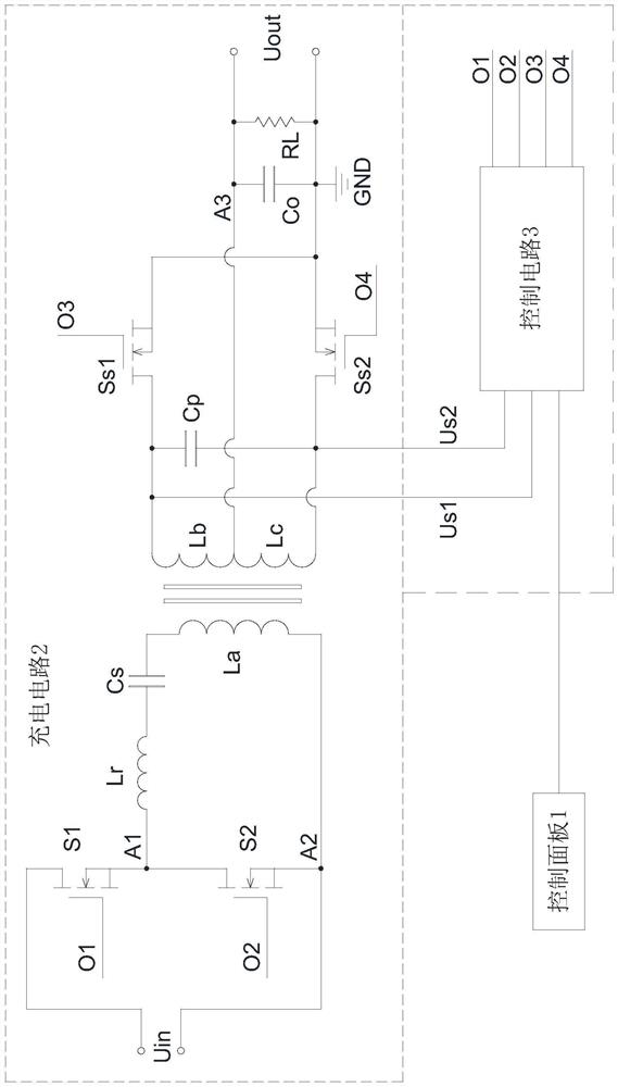
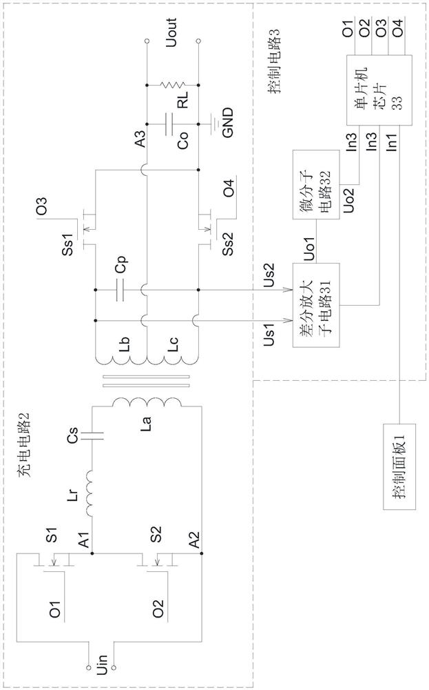
[0026] like Figure 1 to Figure 4 As shown, what this embodiment provides is a high-power battery charger, including a control panel 1, a charging circuit 2 and a control circuit 3, characterized in that:

[0027] The charging circuit 21 includes a voltage input terminal Uin, a transformer, and a voltage output terminal Uout. One end of the voltage input terminal Uin is connected to the D pole of the upper switching tube S1 of the half bridge, and the other end of the voltage input terminal Uin is connected to the lower switching tube S2 of the half bridge. The S pole of the switch tube S1 on the half bridge is connected to form the second node A2, the S pole of the switch tube S1 on the half bridge is connected to the D pole of the switch tube S2 on the half bridge to form the first node A1, and the first node A1 is connected to the second node A2 A2 is connected in series with the primary resonant inductor Lr, the primary resonant capacitor Cs and the primary coil La of the ...

Embodiment 2

[0037] like Figure 5 As shown, this embodiment provides a method for controlling a high-power battery charger, and the high-power battery charger is the high-power battery charger described in Embodiment 1, wherein the control method includes:

[0038] Step A, controlling the first output terminal and the second output terminal of the control circuit according to the signal sent by the control panel, so as to adjust the switching frequency of the upper switching tube S1 of the half bridge and the lower switching tube S2 of the half bridge;

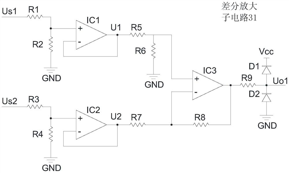
[0039] Step B, detecting the voltage values ​​of the first synchronous rectification detection input terminal Us1 and the second synchronous rectification detection input terminal Us2 to obtain the synchronous rectification conduction value VCp;

[0040] Step C, when the synchronous rectification conduction value VCp is equal to the first preset value, the third output terminal of the control circuit outputs a high level, and the first re...


PUM


Abstract

The invention discloses a high-power battery charger and a control method thereof. The charger comprises a control panel, a charging circuit and a control circuit, wherein the charging circuit comprises a voltage input terminal, a half-bridge upper switching tube, a half-bridge lower switching tube and a transformer, a primary side coil of the transformer, a primary side resonant inductor and a primary side resonant capacitor are connected in series between the S pole and the D pole of the half-bridge lower switching tube; a first secondary-side coil and a second secondary-side coil of the transformer are connected in series, free ends of the first secondary-side coil and the second secondary-side coil are respectively connected with the D pole of a first rectification switch tube and the D pole of a second rectification switch tube, the S poles of the two rectification switch tubes are connected with each other, and the D pole of the first rectification switch tube and the D pole of the second rectification switch tube form two synchronous rectification detection input ends; and the control circuit controls conduction of the half-bridge upper switching tube, the half-bridge lower switching tube, the first rectification switch tube and the second rectification switch tube according to signals of the control panel and the two synchronous rectification detection input ends. The charger is small in size and accurate in synchronous rectification detection.

Description

technical field [0001] The invention relates to a high-power battery charger and a control method thereof. Background technique [0002] With the development of power electronics technology, the energy storage battery capacity of electric vehicles and other equipment is getting larger and larger. In order to speed up the charging speed, it is necessary to use a high-power charger to charge the equipment. In recent years, in order to reduce the loss and size of the charger, resonant soft switching technology has been widely used in high-power chargers. The LCC resonant converter not only has soft switching characteristics, but also has a small frequency range when the output voltage changes, and has good constant current characteristics, which is very suitable as the main circuit of the lithium battery charger. Since the lithium battery charger generally has a low output voltage and a large output current, it is necessary to adopt a synchronous rectification method to reduce...

Claims


Application Information

Patent Timeline
IPC IPC(8): H02J7/00
CPCH02J7/0047H02J7/00712
Inventor 廖鸿飞张福成吴曜丞
Owner 中山市浩成自动化设备有限公司
Why Eureka
Try Eureka