Apparatus for craning machine in atomic reactor

A hoisting device and reactor technology, applied in the direction of reactors, reactor fuel elements, transportation and packaging, etc., can solve the problems of restricted storage places, difficult decontamination operations, complex structures, etc., to improve the efficiency of decontamination operations, simple structure, The effect of reducing space

Inactive Publication Date: 2004-02-18
KK TOSHIBA
View PDF0 Cites 0 Cited by
  • Summary
  • Abstract
  • Description
  • Claims
  • Application Information

AI Technical Summary

Problems solved by technology

[0022] but, Figure 10 The existing hoisting device shown has components such as the lifting drive part 37, the gear box 35, and the gear drive shaft 36 that constitute the lifting device 33, which are large in size and complex in structure, so it is difficult to decontaminate after use.
[0023] In addition, the length of the lifting drive shaft 34 must be set to be greater than the lifting stroke (about 6m) of the lifting frame 32, so due to the height factor of the lifting drive shaft 34, the storage place is limited, or, in the regular maintenance work, become an obstacle when moving other machines
[0024] In addition, for storage, etc., the long drive shaft 34 for lifting is disassembled, and when reassembling, it is necessary to set the horizontal height of the four driving shafts 34 for lifting, and the setting of the horizontal height takes a long time.

Method used


Image

  • Apparatus for craning machine in atomic reactor
  • Apparatus for craning machine in atomic reactor
  • Apparatus for craning machine in atomic reactor

Examples


Embodiment Construction

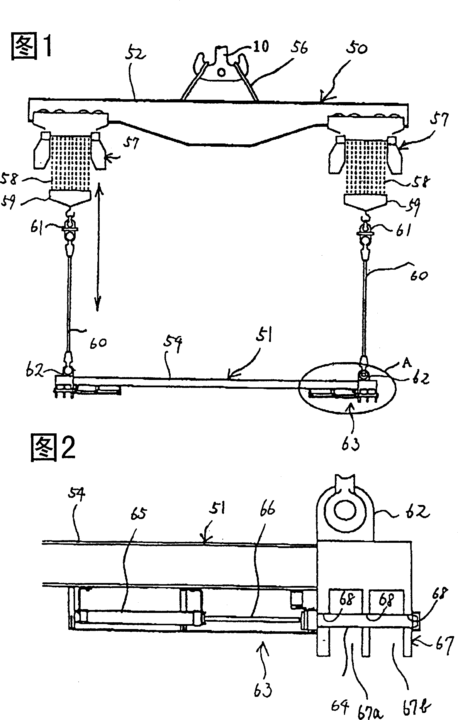
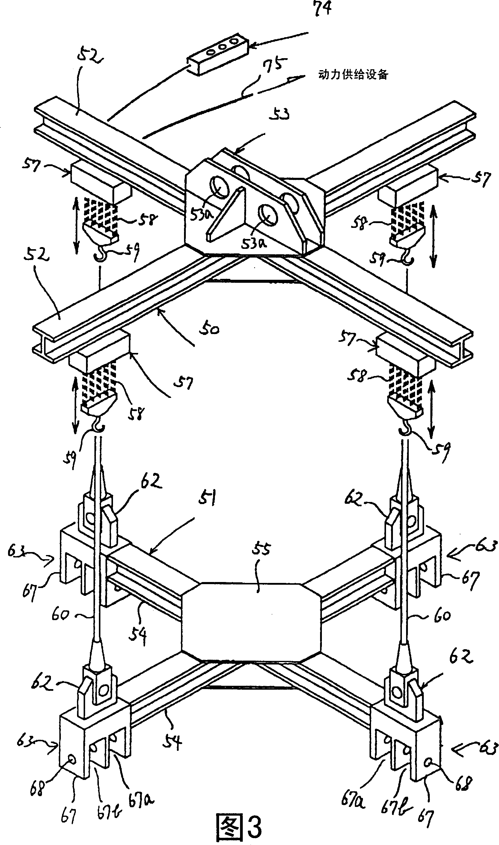
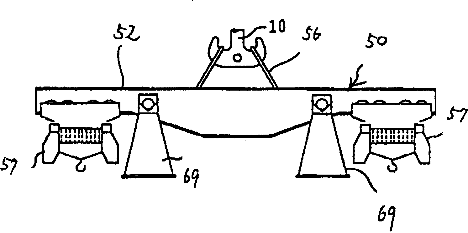
[0056] Below, refer to Figure 1 to Figure 6 A hoisting device (hereinafter simply referred to as a hoisting device) for equipment in a nuclear reactor according to an embodiment of the present invention will be described.

[0057] Fig. 1 is a front view showing a schematic structure of a hoisting device according to an embodiment of the present invention. FIG. 2 is a partially enlarged view showing enlarged portion A of FIG. 1 . Fig. 3 is a perspective view showing a schematic structure of a hoisting device according to an embodiment of the present invention.

[0058] As shown in FIGS. 1 and 3 , the hoisting device of this embodiment includes a support frame (support device) 50 suspended from above the RPV and a lifting frame (elevating device) 51 disposed below the support frame 50 .

[0059] The support frame 50 is formed by intersecting a pair of suspension beams 52 and connecting the intersecting portions with upper connectors 53 . The elevating frame 51 is formed by i...


PUM


Abstract

There is provided a reactor internal equipment hoisting apparatus. The hoisting apparatus includes a supporting unit which is hung down from the upper side of the reactor pressure vessel with an overhead travailing crane installed on the ceiling of the reactor building, and an elevating unit which is arranged below the supporting unit. A coupling/fixing unit is provided to the elevating unit to be releasably coupled with a hoisting lug. Power hoist using a wire rope or a chain is provided to the supporting unit. The elevating unit is hung down from the supporting unit via the rope or the chain to be moved vertically. This reactor internal equipment hoisting apparatus is easy in maintenance and storage.

Description

technical field [0001] The present invention relates to a device for hoisting internal equipment of an atomic reactor, which is used for hoisting internal equipment of an atomic reactor such as a dryer and a sleeve cover installed in an atomic reactor pressure vessel (hereinafter referred to as RPV) of a boiling type atomic reactor (hereinafter referred to as BWR). . Background technique [0002] In the prior art, a plurality of fuel assemblies are housed inside the RPV of the BWR, and these fuel assemblies constitute the core. [0003] Figure 7 It is a longitudinal sectional view showing the furnace structure of BWR. Such as Figure 7 As shown, a core support plate 2 is disposed below the core 1 , and the lower parts of a plurality of fuel assemblies (not shown) constituting the core 1 are supported by the core support plate 2 . Above the core 1 , an upper grid plate 3 is disposed, and the upper portion of the fuel assembly is supported by the upper grid plate 3 . The c...

Claims


Application Information

Patent Timeline
Patent Type & Authority Patents(China)
IPC IPC(8): B66C1/10B66C1/66
CPCB66C1/66B66C1/10
Inventor 秋元淳深道建次郎须藤和雄
Owner KK TOSHIBA
Why Eureka
Try Eureka