
Efficient soaking device of humidifying bottles for pneumology department

A humidification bottle, high-efficiency technology, applied in water supply equipment, sanitary equipment for toilets, chemistry, etc., can solve the problems of waste of disinfectant, inability to control humidification bottles, and low space utilization of disinfection tanks, so as to improve the flushing effect Effect

Inactive Publication Date: 2022-01-11
THE FIRST AFFILIATED HOSPITAL OF HENAN UNIV OF SCI & TECH
View PDF0 Cites 0 Cited by
  • Summary
  • Abstract
  • Description
  • Claims
  • Application Information

AI Technical Summary

Problems solved by technology

[0003] The disinfection and soaking process of the above-mentioned humidification bottle, first of all, due to the lack of professional soaking and disinfection equipment, the staff of the disinfection and supply department need to manually operate the whole process, place heavy objects, adjust the position of the humidification bottle, and take out the heavy objects after soaking. The disinfection process is cumbersome and wastes manpower.
Secondly, during the immersion process, there is a large-scale contact between the humidification bottles, between the humidification bottle and the soaking tank, and between the humidification bottle and the pressure holding weight. Sufficient contact leads to incomplete disinfection and medical risks
Finally, when a large number of humidification bottles are uniformly soaked in the soaking tank in the hospital, the posture of the humidification bottles cannot be controlled. All the humidification bottles are randomly distributed in random postures, resulting in low space utilization of the disinfection tank and waste of disinfectants.

Method used


Image

  • Efficient soaking device of humidifying bottles for pneumology department
  • Efficient soaking device of humidifying bottles for pneumology department
  • Efficient soaking device of humidifying bottles for pneumology department

Examples


Embodiment 1

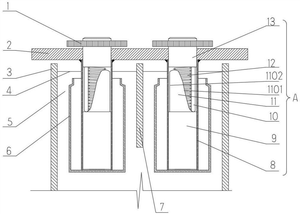
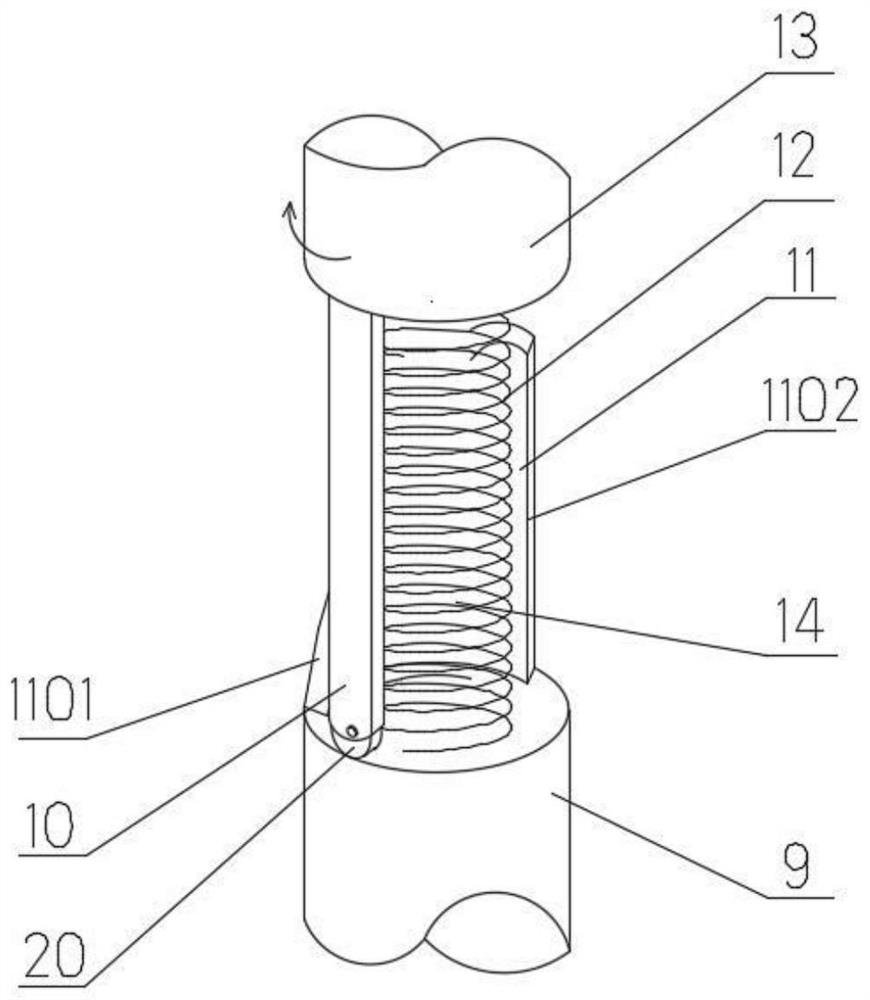
[0027] Such as figure 1 As shown, a high-efficiency soaking device for a respiratory humidification bottle 6 in this embodiment includes a rectangular soaking tank 3 (only part is shown in the figure for illustration). The depth of the soaking tank 3 is 1.5 to 2 times the height of the humidification bottle 6, so as to adapt to the vertical posture of the humidification bottle 6 for immersion and continuous reciprocating ups and downs to achieve the purpose of eliminating blind spots in the dead angle of soaking and disinfection. The length and width of the soaking tank 3 are based on the humidification bottles 6 to be sterilized in the hospital that can be processed in batches. The immersion tank 3 is provided with partition plates 7 staggered along its own length and width, so that the inner cavity of the immersion tank 3 can be divided into multiple soaking postures for a single humidification bottle 6 to be soaked and sterilized separately by the partition plate 7 Limit c...

Embodiment 2

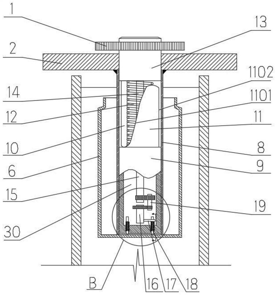
[0040] Such as image 3 As shown, the main structure of this embodiment is similar to that of Embodiment 2, the only difference is that this embodiment is provided with a plurality of pressure rods 18 at the bottom of the sliding shaft 9, the sliding shaft 9 is a hollow shaft and forms a bottom cavity 30 at its lower part . In the bottom cavity 30, there is an actuator for driving the pressure rod 18 to extend out sequentially to sink the humidification bottle 6, and the actuator is linked with the first rotating shaft 13, so that the first rotating shaft 13 can drive the sliding shaft 9 each time. When moving down, a pressing rod 18 is driven to stretch out the pressing humidification bottle 6, so that compared with Embodiment 1, the present embodiment sinks the humidifying bottle 6 through the pressing rod 18, because the pressing rod 18 has a smaller The area of ​​the end wood reduces the contact area with the bottom of the humidification bottle 6 and reduces the dead angl...

Embodiment 3

[0047] The main structure of this embodiment is the same as that of Embodiment 1, the difference is:

[0048] Such as Figure 8 As shown, in the present embodiment, a longitudinal blind hole is provided at the lower end of the push rod 10, and a compression spring 28 and a rolling ball 29 in a compressed state are arranged in the blind hole, and the outer edge of the upper end of the sliding shaft 9 passes through the rolling ball 29 and Slidingly fit with the slope portion 1101 of the pushed piece 11 to reduce friction. Compared with Embodiment 1, the sliding direction of the rolling ball 29 in this embodiment is not limited, so that the push rod 10 has a smaller extrusion force in the sliding fit of the slope portion 1101 , further improving the stability of the structure.


PUM


Abstract

An efficient soaking device for humidifying bottles for the pneumology department comprises a soaking tank, partition plates and a lifting table, the partition plates are used for dividing an inner cavity of the soaking tank into a plurality of soaking posture limiting cavities corresponding to the humidifying bottles in specification, and the lifting table is provided with a plurality of pressing assemblies in one-to-one correspondence with the soaking posture limiting cavities. Each pressing assembly comprises a supporting cylinder vertically fixed to the lower edge of the lifting table, a first rotating shaft rotationally arranged on the upper portion of the supporting cylinder, a driving mechanism used for driving the first rotating shaft to rotate and a sliding shaft arranged on the lower portion of the supporting cylinder in a sliding mode, the first rotating shaft and the sliding shaft are connected through a first reset spring, an eccentrically distributed push rod is arranged at the lower end of the first rotating shaft, a wedge-shaped pushed piece is arranged at the position, corresponding to the rotating track of the push rod, of the upper end of the sliding shaft, one side of the wedge-shaped pushed piece is a slope portion in sliding fit with the lower end of the push rod, and the other side of the wedge-shaped pushed piece is a straight portion allowing the push rod to be rapidly separated from the pushed piece under the tension effect of the first reset spring. The device is easy and convenient to operate and sufficient in disinfection, and disinfection resources are saved.

Description

technical field [0001] The invention relates to the equipment field of the disinfection supply center of the respiratory department, in particular to an efficient soaking device for a humidification bottle used in the respiratory department. Background technique [0002] Oxygen humidification is a rehabilitation equipment and ward nursing consumables. It is mainly used in the oxygen supply system of medical centers. It can be used for emergency oxygen supply in medical units and oxygen inhalation for hypoxic patients. It is convenient and safe to use. , The necessary equipment for oxygen treatment of patients. The conventional external humidification bottle is independent from the outside of the fuselage, which is convenient for observing the water level. However, after long-term use, the humidification bottle will produce scale or moss, which will breed bacteria and cause the oxygen to be unclean. It needs to be thoroughly cleaned and disinfected once every 1-2 weeks to pr...

Claims


Application Information

Patent Timeline
Patent Type & Authority Applications(China)
IPC IPC(8): A61L2/18A61L2/26
CPCA61L2/18A61L2/26A61L2202/23
Inventor 钟文杰霍然李艳
Owner THE FIRST AFFILIATED HOSPITAL OF HENAN UNIV OF SCI & TECH
Learn More