
Intelligent chip removal device for metal chip cutting machine tool and control method thereof

A metal chip and chip conveyor technology, applied in metal processing machinery parts, metal processing equipment, manufacturing tools, etc., can solve problems such as damage, shutdown to clean the chip conveyor, blockage of the chip conveyor, etc., to avoid blockage or damage, The effect of reducing the residual probability and avoiding clogging

Pending Publication Date: 2022-01-11
SHENYANG MASCH TOOL CO LTD
View PDF0 Cites 0 Cited by
  • Summary
  • Abstract
  • Description
  • Claims
  • Application Information

AI Technical Summary

Problems solved by technology

[0002] Metal chip machine tools produce a large amount of chips during the processing, especially in the process of processing non-ferrous metals, there will be a large amount of chips suspended in the cutting fluid, in addition, a very small part of the chips will adhere to the cutting fluid due to the viscosity of the cutting fluid If the scraper plate of the chip conveyor cannot be cleaned in a timely and effective manner, the cutting fluid of the chip conveyor will not flow smoothly. In severe cases, it is necessary to stop the chip conveyor to clean it, and even cause the chip conveyor to be blocked and damaged, reducing the use efficiency of the machine tool

Method used


Image

  • Intelligent chip removal device for metal chip cutting machine tool and control method thereof
  • Intelligent chip removal device for metal chip cutting machine tool and control method thereof
  • Intelligent chip removal device for metal chip cutting machine tool and control method thereof

Examples


Embodiment Construction

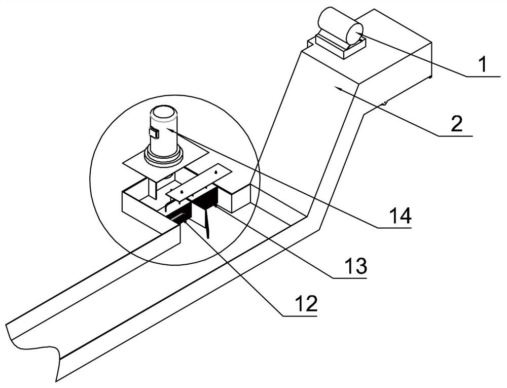
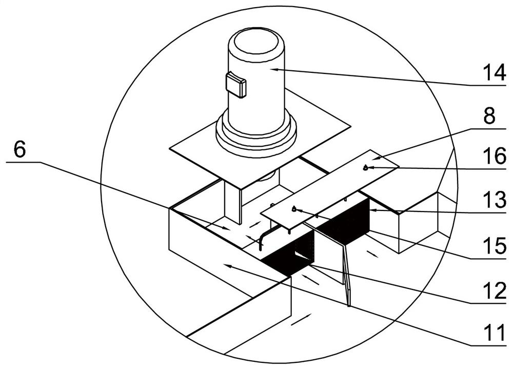
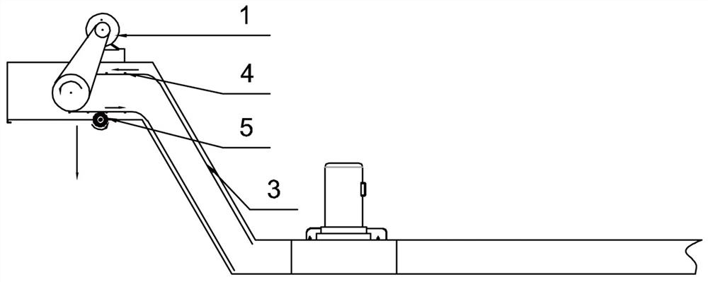
[0026] Such as Figure 1 to Figure 3 As shown, an intelligent chip conveyor for metal chip machine tools includes a chip conveyor belt 3 connected to a chip conveyor 1 through a transmission drive device 1 in a chip discharge channel 2. The transmission drive device 1 uses a servo motor to drive the chip conveyor belt 3. Adjust the chip removal speed; one end of the chip removal channel 2 is at a low horizontal position, with a chip inlet, and the other end is at a high position, with a chip outlet, and the outer wall of the chip removal channel 2 is at a low horizontal position. The flow box 11 of the guide channel 6, the height of the flow box 11 is consistent with the height of the opening, and the upper edge of the opening is higher than the height of the chip mixture in the chip removal channel 2; in the flow guide channel 6 of the flow box 11, I A circulation pump 14 is provided on the top of the flow box 11 for the first-stage filter screen 12 and the second-stage filte...


PUM


Abstract

The invention relates to an intelligent chip removal device for a metal chip cutting machine tool. The intelligent chip removal device is characterized in that a chip removal channel is internally connected with a cut chip conveying belt through a conveying driving device, one end of the chip removal channel is positioned at a horizontal low position and is provided with a cut chip inlet, and the other end of the chip removal channel is positioned at a high position and is provided with a cut chip outlet; an opening is formed in the outer wall, located at the horizontal low position, of the chip removal channel, a flow box with a flow guide channel is arranged at the opening, the height of the flow box is consistent with that of the opening, and the upper edge of the opening is higher than that of cut chip mixed liquid in the chip removal channel; and a first-stage filter screen and a second-stage filter screen are sequentially arranged in the flow guide channel of the flow box, a circulating pump is arranged at the top of the flow box, and a working part at the bottom of the circulating pump is inserted into the flow guide channel. The chip removal device has the characteristics of automatically, efficiently and timely cleaning chips in the cutting fluid and avoiding blockage of the chip removal device, and is a novel intelligent chip removal device for the machine tool.

Description

technical field [0001] The invention relates to an intelligent chip conveyor for a metal chip machine tool and a control method thereof, and belongs to the technical field of machine tool accessories. Background technique [0002] Metal chip machine tools produce a large amount of chips during the processing, especially in the process of processing non-ferrous metals, there will be a large amount of chips suspended in the cutting fluid, in addition, a very small part of the chips will adhere to the cutting fluid due to the viscosity of the cutting fluid If the scraper plate of the chip conveyor cannot be cleaned in time and effectively, the cutting fluid of the chip conveyor will not flow smoothly. In severe cases, it is necessary to stop the chip conveyor to clean it, and even cause the chip conveyor to be blocked and damaged, reducing the efficiency of the machine tool. Contents of the invention [0003] The technical problem to be solved by the invention is to provide a...

Claims


Application Information

Patent Timeline
IPC IPC(8): B23Q11/00B23Q11/10
CPCB23Q11/0042B23Q11/1069
Inventor 罗和平刘洪强王树青王锐李涛宋辰李太松张来民张朝麟房立娜
Owner SHENYANG MASCH TOOL CO LTD
Learn More