Bailey beam and distribution beam connecting device suitable for multiple occasions

A technology for connecting devices and distributing beams, applied in bridges, bridge parts, bridge construction, etc., can solve the problems of large lateral reinforcement size, reinforcement, and inability to reinforce, so as to improve structural integrity and stability, improve structural integrity, The effect of many occasions

Pending Publication Date: 2022-01-11
中交四航局第四工程有限公司 +1
View PDF16 Cites 3 Cited by
  • Summary
  • Abstract
  • Description
  • Claims
  • Application Information

AI Technical Summary

Problems solved by technology

[0004] One of the purposes of the present invention is at least to address the fact that in the prior art it is impossible to integrally reinforce the overlapping joints at the joints between the Bailey beam and the distribution beam, and at the overlapping joints there are many supporting structures and the size of the transverse reinforcement is relatively small. For the problem that it is too large to be reinforced, it provides a connection device between Bailey beam and distribution beam that is suitable for many occasions. The connection device between Bailey beam and distribution beam can integrate the distribution beam and Bailey beam at the same time type reinforcement, and the connecting device between the Bailey beam and the distribution beam can also be used at the connection node of the top chord of the Bailey beam and where there are many structures at the connection node, so that the connection between the distribution beam and the Bailey beam is firm and avoids Problems affecting structural safety such as distribution beam collapse, overturning and displacement of distribution beam relative to Bailey beam occurred

Method used


Image

  • Bailey beam and distribution beam connecting device suitable for multiple occasions
  • Bailey beam and distribution beam connecting device suitable for multiple occasions
  • Bailey beam and distribution beam connecting device suitable for multiple occasions

Examples


Embodiment 1

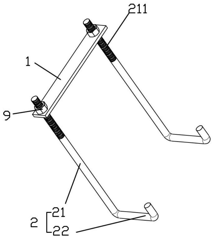
[0061] image 3 The structure of the connection device between the Bailey beam and the distribution beam of the exemplary embodiment of the present invention is shown. The connection device between the Bailey beam and the distribution beam of this embodiment includes a pressing member 1 and two fixed rods 2 arranged side by side. The fixed rod 2 includes a straight rod segment 21 and a hook-shaped segment 22 connected to one end of the straight rod segment 21. The other ends of the two straight rod segments 21 are detachably connected through the pressing member 1. The fixed rod adopts round steel, such as Figure 5 As shown, the pressing member 1 is a steel plate structure with locking holes 101 at both ends for pressing, and the straight rod section 21 of the fixing rod 2 is inserted into the locking hole 101 of the pressing member 1, and One end of the straight bar section 21 that penetrates into the pressing piece 1 is provided with a connecting thread 211, and the pressi...

Embodiment 2

[0063] Figure 6 The structure of the connection device between the Bailey beam and the distribution beam according to an exemplary embodiment of the present invention is shown. The structure of the part 1 is the same as that in the embodiment 1, and the straight rod section 21 of the fixing rod 2 is also inserted into the locking hole 101 of the pressing part 1 and locked and fixed by the nut 9, which is different from the embodiment 1. What is more, the connecting device between the Bailey beam and the distribution beam of the present embodiment also includes a connecting rod 4 fixedly connecting the two fixed rods 2, and the connecting rod 4 connects the two fixed rods 2 arranged side by side, so that the two fixed rods 2 At the same time, the connecting rod 4 and the pressing piece 1 are connected to form an overall structure. On the one hand, the structural integrity and stability of the connecting device between the Bailey beam and the distribution beam are improved, and...

Embodiment 3

[0066] The structure of the connecting device between the Bailey beam and the distribution beam of the present embodiment is further improved on the basis of embodiment 2, such as Figure 10-11 As shown, the connecting device structure between the Bailey beam and the distribution beam also includes a pressing member 1 and two fixed rods 2 arranged side by side. The fixed rod 2 includes a straight rod section 21 and a The hook section 22, the other ends of the two straight bar sections 21 are detachably connected through the pressing piece 1, and the connecting device structure between the Bailey beam and the distribution beam also includes a connecting rod 4 and a reverse hook section 23 , the connecting rod 4 is connected to the straight bar section 21, and the reverse hook section 23 is connected to the junction of the straight bar section 21 and the hook section 22, but the arrangement direction is opposite to that of the hook section 22, that is, it is opposite to the hook ...


PUM


Abstract

The invention relates to the technical field of bridge cast-in-place box beam formwork support system erection construction, in particular to a bailey beam and distribution beam connecting device suitable for multiple occasions, the bailey beam and distribution beam connecting device comprises a pressing piece and two fixing rods arranged side by side, each fixing rod comprises a straight rod section and a hook-shaped section connected to one end of the straight rod section, the other end of each of the two straight rod sections is detachably connected through the pressing piece, the bailey beam and distribution beam connecting device further comprises a connecting rod for fixedly connecting the two fixing rods, and the connecting rod is of a telescopic structure. The connecting device is easy to operate and convenient to use, a user can directly bend down to insert the connecting device from a gap of the bailey beam when standing on the upper portion of the bailey beam, the hook-shaped section hooks and fixes the bailey beam, the problem that U-bolts cannot be directly inserted and fixed from the upper portion is solved, the distance between the two fixing rods can be freely adjusted through the connecting rod of the telescopic structure, and the device is suitable for multiple occasions.

Description

technical field [0001] The invention relates to the technical field of construction of a bridge cast-in-place box girder formwork support system, in particular to a connecting device for a Bailey beam and a distribution beam applicable to multiple occasions. Background technique [0002] Bailey beams have the advantages of rapid erection and strong mobility, and are widely used in engineering construction processes, such as construction platforms, engineering access bridges, temporary bridges across rivers and support platform foundations. The Bailey beam is a truss beam assembled from Bailey frames, with multiple truss units 6a, such as figure 1 As shown, each truss unit 6a includes an upper chord 61 and a lower chord 62, a plurality of vertical support rods 63 are vertically arranged between the upper chord 61 and the lower chord 62, and the upper chord 61 is connected to the vertical The support bar 63 is reinforced, and the truss unit structure that connects the lower c...

Claims


Application Information

Patent Timeline
Patent Type & Authority Applications(China)
IPC IPC(8): E01D15/133E01D19/00
CPCE01D15/133E01D19/00
Inventor 廖光磊王显录贺超熊鹏颜其平
Owner 中交四航局第四工程有限公司
Why Eureka
Try Eureka