New energy automobile brake

A new energy vehicle and brake technology, applied in the direction of brake types, drum brakes, brake components, etc., can solve the problems of reducing the service life of brakes and wheels, troublesome replacement, high replacement cost, etc., to reduce the temperature and prolong the use time Effect

Pending Publication Date: 2022-01-11
马日色约
View PDF0 Cites 0 Cited by
  • Summary
  • Abstract
  • Description
  • Claims
  • Application Information

AI Technical Summary

Problems solved by technology

[0003] Regardless of whether it is a drum brake or a disc brake, the braking principle is that the brake shoe presses the rotating surface. This surface is called a drum, which is an indispensable component for the drum brake to achieve the braking effect. It is used to decelerate and brake the wheel hub of the car. Therefore, when braking, the driver needs to apply a certain force to drive the brake to work. Some brakes do not have a power-assisted structure, which causes the driver to use a lot of power when braking. When braking, the friction between the rotating elements connected to the brake and the wheel (or transmission shaft) prevents the rotation or rotation of the wheel. At this time, high temperature is generated, which will reduce the service life of the brake and the wheel. The brake pads on the brake pads are consumable components, and it is troublesome to replace them. If the heat is severe, the entire brake will be damaged, and the replacement cost is very high. If the temperature of the entire brake is cooled during braking, the use of the brake pads and the entire brake can be extended. life

Method used


Image

  • New energy automobile brake
  • New energy automobile brake
  • New energy automobile brake

Examples


Embodiment Construction

[0029] In order to make the technical means, creative features, goals and effects achieved by the present invention easy to understand, the present invention will be further described below in conjunction with specific embodiments.

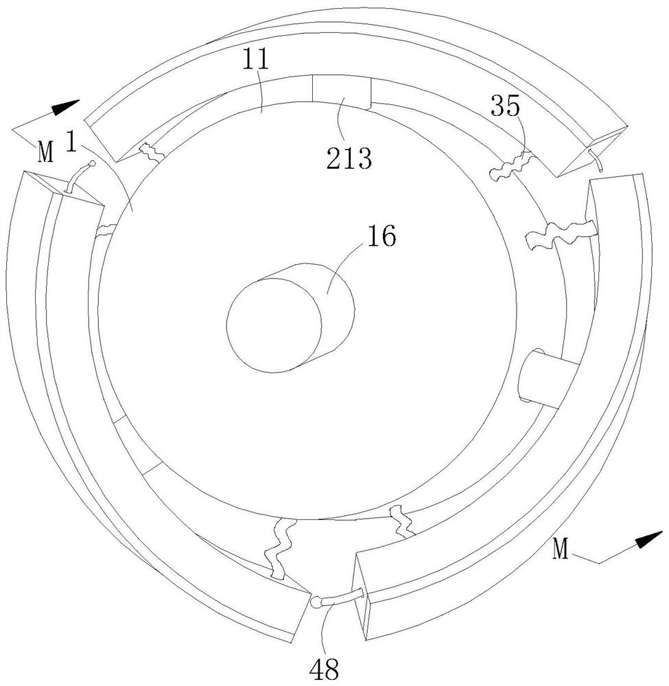
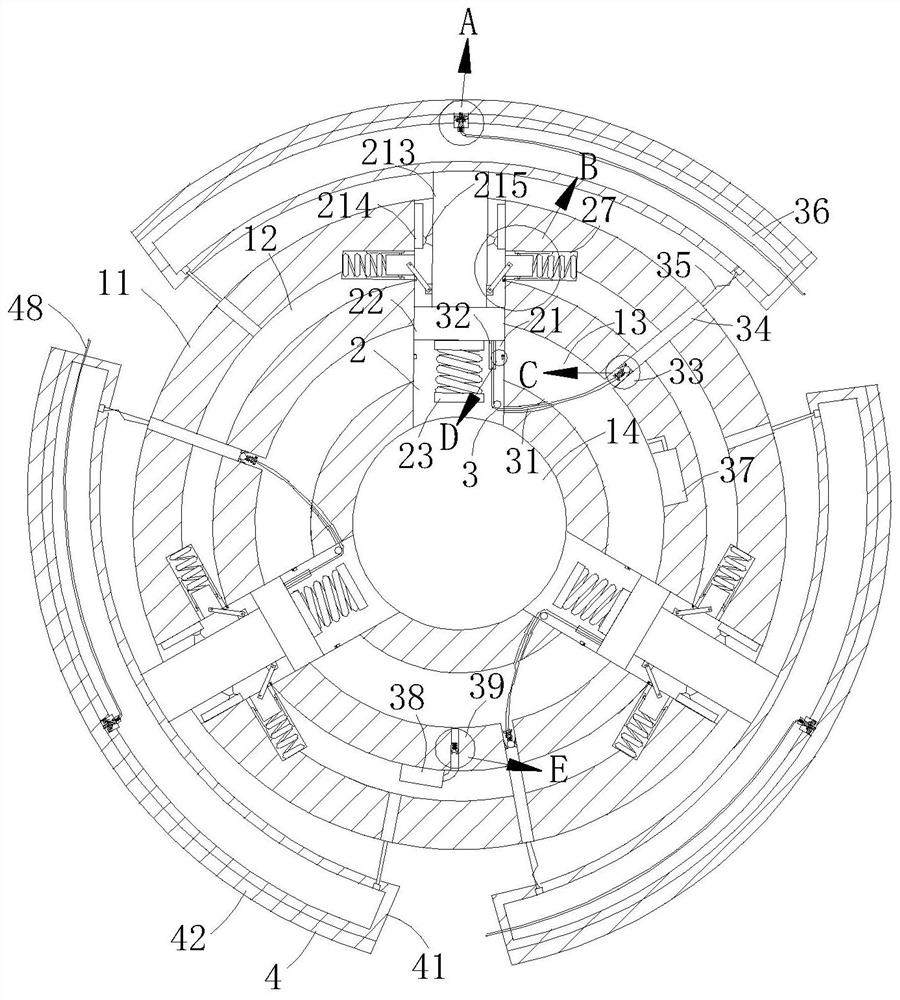
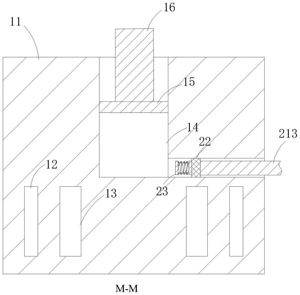
[0030] Such as Figure 1-Figure 8 As shown, a new energy vehicle brake according to the present invention includes a disc body mechanism 1, a hydraulic mechanism 2, a heat dissipation mechanism 3 and a braking mechanism 4, and a hydraulic mechanism 2 is arranged inside the disc body mechanism 1, and the hydraulic mechanism A heat dissipation mechanism 3 is arranged on the periphery of the mechanism 2, and the brake mechanism 4 is arranged on the periphery of the disc mechanism 1. The brake mechanism 4 is fixedly connected to the hydraulic mechanism 2, and the brake mechanism 4 and the heat dissipation Mechanisms 3 communicate with each other; the main body of the disc body mechanism 1 is a steel body, and a pipe channel is arranged inside, the hyd...


PUM


Abstract

The invention relates to the technical field of brakes, in particular to a new energy automobile brake. The new energy automobile brake comprises a disc body mechanism, a hydraulic mechanism, a heat dissipation mechanism and a brake mechanism, the hydraulic mechanism is arranged in the disc body mechanism, the heat dissipation mechanism is arranged on the periphery of the hydraulic mechanism, the brake mechanism is arranged on the periphery of the disc body mechanism, the brake mechanism is fixedly connected with the hydraulic mechanism, and the brake mechanism communicates with the heat dissipation mechanism. A main body of the disc body mechanism is a steel solid body, a pipe channel is formed in the disc body mechanism and used for providing circulating water for the heat dissipation mechanism, the hydraulic mechanism receives pressure to control the brake mechanism to stretch out and draw back, the brake mechanism brakes wheels through friction, a quick-wear brake pad on the surface of the brake mechanism can be conveniently replaced, the heat dissipation mechanism can inject water into the brake mechanism during braking, water is used for absorbing heat generated by friction of the brake pad during braking, the wheels and a brake are protected, and the service life is prolonged.

Description

technical field [0001] The invention relates to the technical field of brakes, in particular to a new energy vehicle brake. Background technique [0002] In modern life, the car is an indispensable tool for people to travel. When the car is running at high speed, good brakes are also indispensable. The brakes used in cars are almost all friction type, which can be divided into two types: drum type and disc type. kind. [0003] Regardless of whether it is a drum brake or a disc brake, the braking principle is that the brake shoe presses the rotating surface. This surface is called a drum, which is an indispensable component for the drum brake to achieve the braking effect. It is used to decelerate and brake the wheel hub of the car, so when braking, the driver needs to apply a certain force to drive the brake to work. Some brakes do not have a power-assisted structure, which causes the driver to use a lot of power when braking. When braking, the friction between the rotatin...

Claims


Application Information

Patent Timeline
IPC IPC(8): F16D51/14F16D69/04F16D65/09F16D65/833
CPCF16D51/14F16D69/0416F16D65/09F16D65/833F16D2121/04F16D2051/001
Inventor 马日色约崔哲博
Owner 马日色约
Why Eureka
Try Eureka