
New energy disc type brake disc and use method thereof

A technology of brake discs and new energy, applied in the direction of brake discs, brakes, axial brakes, etc., can solve the problems of reduced air flow, waste of resources, waste of resources and economic losses, etc., to prevent rear-end collision accidents and accurate replacement time , Improve the effect of safety performance

Pending Publication Date: 2022-01-11
李远志
View PDF0 Cites 0 Cited by
  • Summary
  • Abstract
  • Description
  • Claims
  • Application Information

AI Technical Summary

Problems solved by technology

[0004] The wear degree of the existing disc brake disc main body is generally determined by the mileage or the use time to determine whether it needs to be replaced, and the main body of the disc brake disc will have a large wear degree difference at the same mileage according to different road conditions. In addition, if the main body of the brake disc is not commonly used in some cars, if the main body of the brake disc is determined simply according to the time or mileage, it will cause the main body of the part of the brake disc to be replaced when it does not need to be replaced, resulting in a waste of resources. The same is true for the replacement of brake fluid. The time of invasion is also different, so it is impossible to know the exact replacement time based on the mileage and usage time alone. Extracting and replacing will cause a large waste of resources and economic losses, and the existing brake disc body can only actively brake. In use, if people are distracted at high speed, they will not be able to decelerate effectively and timely, which will easily cause accidents. At the same time, some disc brakes have ventilation holes for heat dissipation, but in actual use, the brakes are in a deceleration state. As the speed decreases, the wind will Gradually decrease, so that the air flow sometimes cannot cool the brake pads in time, so there is an urgent need for a disc brake disc to solve the above problems

Method used


Image

  • New energy disc type brake disc and use method thereof
  • New energy disc type brake disc and use method thereof
  • New energy disc type brake disc and use method thereof

Examples


Embodiment Construction

[0031] The following will clearly and completely describe the technical solutions in the embodiments of the present invention with reference to the accompanying drawings in the embodiments of the present invention. Obviously, the described embodiments are only some, not all, embodiments of the present invention. Based on the embodiments of the present invention, all other embodiments obtained by persons of ordinary skill in the art without making creative efforts belong to the protection scope of the present invention.

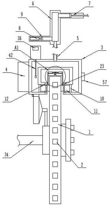
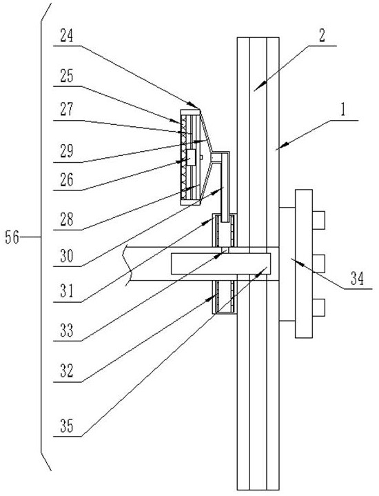
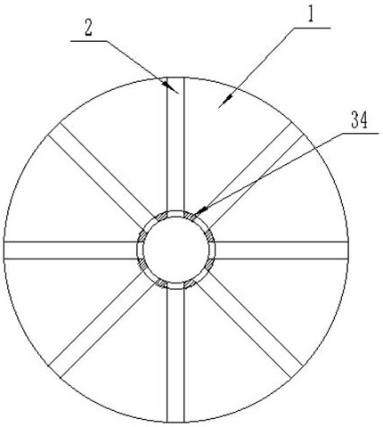
[0032] see Figure 1-6 , the present invention provides a technical solution: a new energy disc brake disc, including a brake disc main body 1, a brake caliper 3 and a control box 4, the inner position of the brake disc main body 1 is uniformly provided with several cooling holes 2, The central position of the main body of the brake disc 1 is fixedly installed with a connecting shaft 34, and the central position of the upper end of the brake caliper 3 is fixed...


PUM


Abstract

The invention discloses a new energy disc type brake disc and a use method thereof. The brake disc comprises a brake disc body, a brake caliper and a control box, a plurality of heat dissipation holes are evenly formed in the brake disc body, and a connecting shaft is fixedly installed in the center of the brake disc body. A speed measuring module detects the running speed of a vehicle, if the detected speed is larger than the threshold value, a distance measuring module detects the distance between the vehicle and a front vehicle, and if the detected distance is smaller than the threshold value, data is transmitted into the control box, the control box starts an electric push rod to extend so as to drive a second piston block to move, brake oil in a storage box is injected into the brake caliper through an oil conveying pipe, thus a brake shoe is extruded to move to clamp and decelerate the brake disc body until the vehicle distance is prolonged to a proper distance, auxiliary braking is performed, rear-end collision accidents caused by untimely braking due to distraction are prevented, and the safety performance of a brake system is greatly improved.

Description

technical field [0001] The invention relates to the field of automobile equipment, in particular to a new energy disc brake disc and a method for using the same. Background technique [0002] The main body of the disc brake disc uses a metal block (disc) instead of a drum. There is a flat brake shoe on both sides of the brake disc. When the oil pressure from the brake master cylinder is sent to the sub-cylinder, the brake shoe is clamped to the brake disc. , In order to achieve the effect of brake tightness, it has been widely used in front wheels at present. Some high-end vehicles are equipped with four-wheel disc brakes, which do not need to adjust the brake clearance and are easy to maintain. [0003] Disc brakes are sometimes called disc brakes. Some disc brakes have many circular ventilation holes drilled on the disc surface, or cut out ventilation slots or prefabricated rectangular ventilation holes on the end face of the disc to become ventilated disc brakes; Ventila...

Claims


Application Information

Patent Timeline
IPC IPC(8): F16D65/18F16D66/02F16D65/847F16D65/092F16D65/12F16D55/225G01D21/02B60T7/12F16D121/04
CPCF16D65/18F16D66/024F16D65/847F16D65/092F16D65/128F16D55/225G01D21/02B60T7/12F16D2065/1328F16D2121/04B60T2201/022
Inventor 李远志
Owner 李远志
Features
  • Generate Ideas
  • Intellectual Property
  • Life Sciences
  • Materials
  • Tech Scout
  • Unparalleled Data Quality
  • Higher Quality Content
  • 60% Fewer Hallucinations
Learn More