Galvanometer control detection device

A technology for controlling detection and detectors, which is applied in the direction of measuring devices, program control, and electrical devices, etc., can solve problems such as weak self-inspection ability, effect deviation, current, voltage, temperature and other data cannot be fed back in time, to ensure the best Optimum state, improve self-test ability, and avoid the effect of large temperature drift

Pending Publication Date: 2022-01-11
GREE ELECTRIC APPLIANCES INC
View PDF6 Cites 0 Cited by
  • Summary
  • Abstract
  • Description
  • Claims
  • Application Information

AI Technical Summary

Problems solved by technology

The existing galvanometer control system has weak self-inspection ability, and the current, voltage, temperature and other data cannot be fed back in time, which affects the control of the swing motor. The repeated positioning accuracy of the swing motor is low, and the laser processing or processing tasks cannot be accurately completed, and the effect is biased.

Method used


Image

  • Galvanometer control detection device
  • Galvanometer control detection device
  • Galvanometer control detection device

Examples


Embodiment Construction

[0032] In order to make the purposes, technical solutions and advantages of the embodiments of the present application clearer, the technical solutions in the embodiments of the present application will be clearly and completely described below in conjunction with the drawings in the embodiments of the present application. Obviously, the described embodiments It is a part of the embodiments of this application, but not all of them. All other embodiments obtained by persons of ordinary skill in the art based on the embodiments in the present application without creative efforts shall fall within the protection scope of the present application.

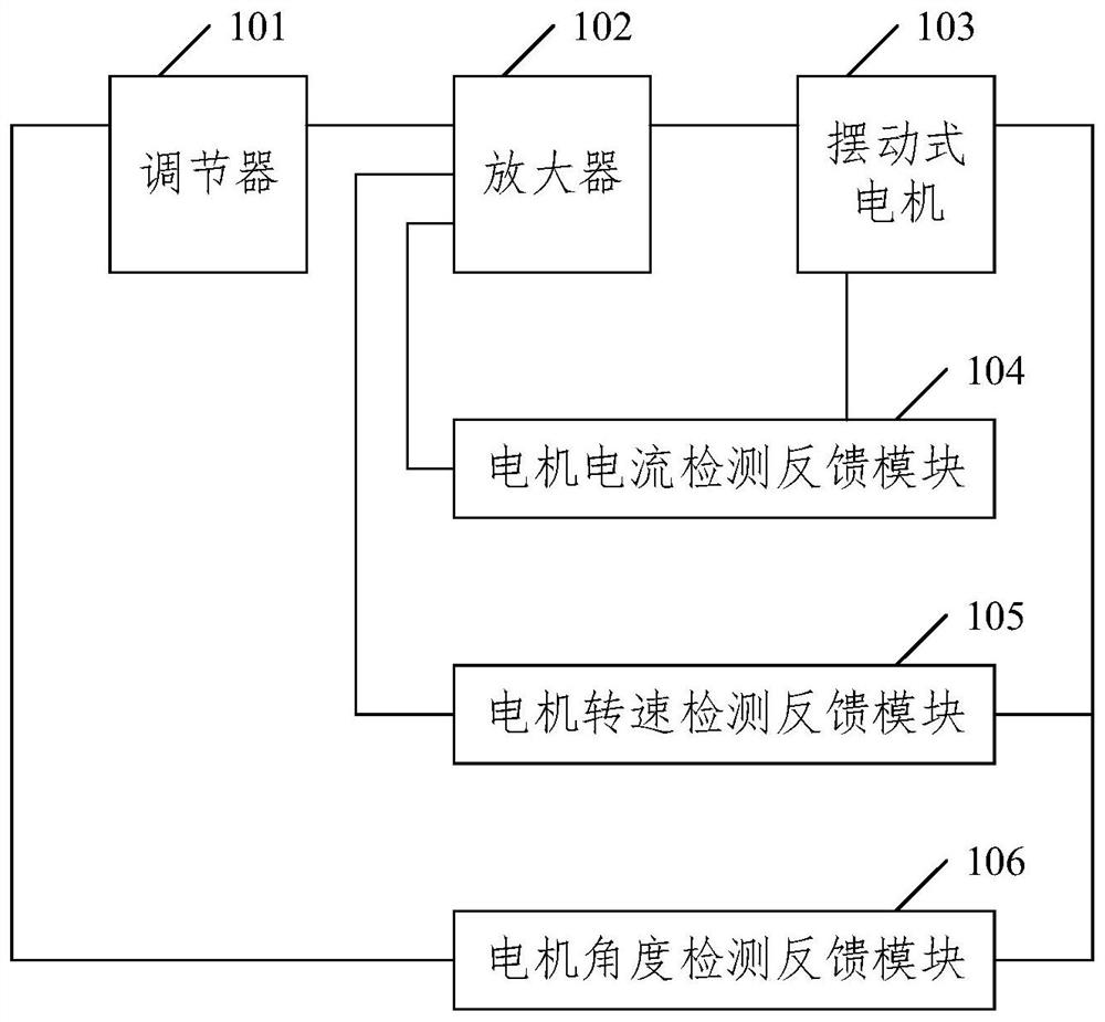
[0033] The inventor finds by analyzing the existing vibrating mirror control device, such as figure 1 As shown, the vibrating mirror control device includes a regulator 101 , an amplifier 102 , a swing motor 103 , a motor current detection and feedback module 104 , a motor speed detection and feedback module 105 and a motor angle detect...


PUM


Abstract

The invention relates to a galvanometer control detection device, and relates to the technical field of motor control detection. The galvanometer control detection device comprises a regulator, an amplifier, a swing type motor, a driving current detection module and a temperature detection module. The output end of the regulator is connected with the first input end of the amplifier, the output end of the amplifier is connected with the input end of the swing type motor, the first output end of the swing type motor is connected with the input end of the temperature detection module, and the output end of the temperature detection module is connected with the first input end of the regulator; the input end of the driving current detection module is connected with the output end of the amplifier, and the output end of the driving current detection module is connected with the second input end of the regulator. The galvanometer control detection device is used for solving the problem that only feedback protection is carried out on the swing type motor at present, and protection for a drive control circuit of the swing type motor is lacked.

Description

technical field [0001] The present application relates to the technical field of motor control detection, in particular to a vibrating mirror control detection device. Background technique [0002] Galvanometer applications include laser marking, 3D printing, laser drilling, laser welding, laser cutting, laser cleaning, laser medical, biomedical and ophthalmic imaging. The galvanometer is the core component of the laser system. The galvanometer can deflect and reflect the laser. The rotation of the oscillating motor makes the mirror deflect to reflect the laser deflection angle. The oscillating motor is controlled by the circuit and detected for movement and self-inspection. [0003] The galvanometer control system includes a closed-loop feedback control system, a detection system, a power amplification system, a compensation system, a signal conditioning system and an angle sensor. The existing galvanometer control system has weak self-inspection ability, and the current, ...

Claims


Application Information

Patent Timeline
Patent Type & Authority Applications(China)
IPC IPC(8): G05B23/02G01K7/22G01K13/00G01R19/00
CPCG05B23/0213G01R19/0092G01K13/00G01K7/22G01K2219/00G05B2219/24065
Inventor 林帆康燕黄斌金子皓樊柳芝
Owner GREE ELECTRIC APPLIANCES INC
Why Eureka
Try Eureka