Energy transfer type single battery voltage management circuit
A battery cell and voltage management technology, applied in battery circuit devices, charge equalization circuits, circuit devices, etc., can solve the problems of poor cycle life and capacity utilization of battery packs, combustion, battery pack performance attenuation, etc.
- Summary
- Abstract
- Description
- Claims
- Application Information
AI Technical Summary
Problems solved by technology
Method used
Image

Examples
Embodiment Construction
[0016] In order to make the purpose, technical solutions and advantages of the embodiments of the present invention more clear, the technical solutions in the embodiments of the present invention will be clearly and completely described below in conjunction with the accompanying drawings in the embodiments of the present invention. Obviously, the described embodiments It is a part of embodiments of the present invention, but not all embodiments. Based on the embodiments of the present invention, all other embodiments obtained by persons of ordinary skill in the art without making creative efforts belong to the protection scope of the present invention.
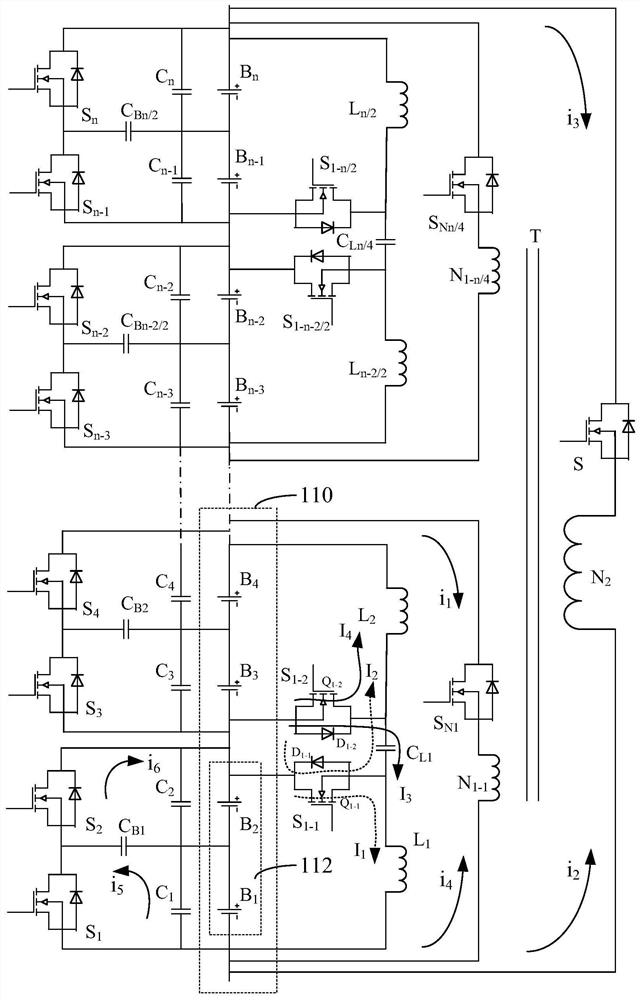
[0017] Such as figure 1 As shown, an energy transfer type battery cell voltage management circuit is used to manage multiple battery cells B connected in series 1 ~B n The battery pack is divided into a plurality of battery units 110, each battery unit 110 includes a plurality of battery rows 112 connected in series, and the...
PUM
 Abstract
Description
Claims
Application Information
PatSnap Eureka turns technology decisions into work you can execute. Powered by our Innovation Knowledge Graph, it runs expert workflows across engineering, life sciences, materials and intellectual property. Get your review-ready output in minutes.


