Liquefied air energy storage system adopting liquefied natural gas for cold storage and method thereof

A technology of liquefied natural gas and liquefied air, which is applied in the field of energy storage, can solve problems such as difficult recovery of cold energy, decline of cold energy grade, complex equipment structure, etc., and achieve the effect of improving technical economy, improving cold storage efficiency, and accelerating popularization and application

Active Publication Date: 2022-01-14
势加透博(上海)能源科技有限公司
View PDF5 Cites 3 Cited by
  • Summary
  • Abstract
  • Description
  • Claims
  • Application Information

AI Technical Summary

Problems solved by technology

In the process of realizing the present invention, the inventors found that there are at least the following problems in the prior art: it is difficult to recover the cold energy released by the liquefied air during the gasification process, and the conventional packed bed cold storage device is used, the equipment structure is complex, the volume is large, and Due to the problem of internal temperature uniformity, it will lead to a decrease in the grade of cold energy and irreversible loss

Method used


Image

  • Liquefied air energy storage system adopting liquefied natural gas for cold storage and method thereof

Examples


Embodiment Construction

[0041] Embodiments of the present invention are described in detail below, examples of which are shown in the drawings, wherein the same or similar reference numerals designate the same or similar elements or elements having the same or similar functions throughout. The embodiments described below by referring to the figures are exemplary only for explaining the present invention and should not be construed as limiting the present invention. On the contrary, the embodiments of the present invention include all changes, modifications and equivalents coming within the spirit and scope of the appended claims.

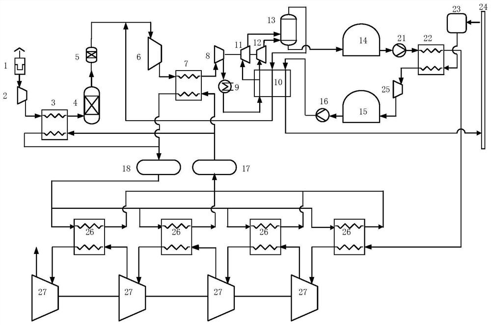
[0042] figure 1 It is a structural schematic diagram of a liquefied air energy storage system using liquefied natural gas cold storage proposed by an embodiment of the present invention.

[0043] see figure 1, the first aspect of the present invention provides a liquefied air energy storage system using liquefied natural gas for cold storage, including: a liquefied air e...


PUM


Abstract

The invention provides a liquefied air energy storage system adopting liquefied natural gas for cold storage. The liquefied air energy storage system comprises the liquefied air energy storage system, a natural gas pipeline network, a condensation evaporator, a liquefied natural gas expansion machine, a liquefied natural gas storage tank, a liquefied natural gas booster pump and a liquid air energy release power generation system, wherein the liquefied air energy storage system is used for converting air in the atmosphere into liquid air and recycling cold energy generated when the liquid air is gasified; a natural gas pipeline network; the condensation evaporator is used for exchanging heat in the liquid air gasification process and the high-pressure gaseous natural gas liquefaction process; the liquefied natural gas expansion machine is used for expanding the high-pressure liquefied natural gas from the condensation evaporator to low pressure and doing work to recover pressure energy; a liquefied natural gas storage tank; the liquefied natural gas booster pump is used for enabling the boosted liquefied natural gas to enter the liquefied air energy storage system and recycling the cold energy generated when the liquid air is gasified; and the liquid air energy release power generation system is used for heating the gaseous compressed air from the condensation evaporator and utilizing compressed air expansion to do work to generate power. The invention further provides a liquefied air energy storage method adopting the liquefied natural gas for cold storage.

Description

technical field [0001] The invention relates to the technical field of energy storage, in particular to a liquefied air energy storage system and method thereof using liquefied natural gas for cold storage. Background technique [0002] Liquefied air energy storage is a new type of energy storage technology. When storing energy, the system uses electricity to drive the air liquefaction device to generate liquefied air, which is stored in a low-temperature storage tank. When the energy is released, the liquefied air in the low-temperature storage tank is pressurized and heated. , and then drive the expander to generate power. Due to the high density of liquefied air, the volume of the storage tank can be greatly reduced. In the process of realizing the present invention, the inventors found that there are at least the following problems in the prior art: it is difficult to recover the cold energy released by the liquefied air during the gasification process, and the conventi...

Claims


Application Information

Patent Timeline
Patent Type & Authority Applications(China)
IPC IPC(8): F25J1/00F28D20/00F01D13/02F01D15/10
CPCF25J1/0012F25J1/005F25J1/007F28D20/00F01D15/10F01D13/02F28D2020/006F25J1/0035F25J2230/30F25J2230/04F25J1/004F25J1/0045F25J2240/90F25J1/0242F25J1/0022F25J2210/62F25J2210/40F25J1/0224F25J1/0042F25J1/0221F25J1/0251Y02E60/14Y02E60/16
Inventor 张学锋郑开云俞国华陶林白江涛
Owner 势加透博(上海)能源科技有限公司
Why Eureka
Try Eureka