Modular permanent magnet direct drive motor used on ball mill

A permanent magnet direct drive, ball mill technology, applied in electromechanical devices, magnetic circuits, synchronous machines, etc., can solve the problems of reducing motor efficiency, sweeping, cumbersome transmission mechanism, etc., reducing the amount of permanent magnets, convenient installation and disassembly, avoiding The effect of the sweeping phenomenon

Pending Publication Date: 2022-01-14
河南全新机电设备有限公司
View PDF0 Cites 0 Cited by
  • Summary
  • Abstract
  • Description
  • Claims
  • Application Information

AI Technical Summary

Problems solved by technology

[0002] The ball mill is a kind of equipment for crushing materials. Its basic principle is to use the rotating force to lift the steel balls in the cylinder to a certain height and drop them on the materials. The materials are crushed by the mutual contact between the steel balls and the materials. The traditional ball mill needs to be equipped with a cumbersome transmission mechanism. In the traditional ball mill, the output shaft of the motor drives the pinion through the reducer, and the pinion drives the large gear to drive the rotation of the drum. Due to the large diameter of the ball mill drum, the drum is used as a permanent magnet direct drive motor. Rotor, in mechanical manufacturing, material processing and assembly will cause the deformation of the drum, the ball mill is too long and its weight is too large, as well as the gap and wear of the support system will cause the eccentric swing of the equipment during operation
The eccentric swing of the mill drum will cause the gap between the stator core and the rotor core to be uneven, reduce the efficiency of the motor, increase the temperature rise of the motor, generate vibration and noise, and even cause collisions between the stator core and the rotor core in severe cases, resulting in sweeping Bore phenomenon, damage the motor
Therefore, in the manufacture of products, only by increasing the gap between the stator core and the rotor core to prevent the motor from sweeping, it is necessary to stop the machine frequently to calibrate and adjust the gap, and the gap between the stator core and the rotor core of the direct drive permanent magnet motor increases. , the amount of permanent magnets will increase, and the cost of the motor will increase

Method used


Image

  • Modular permanent magnet direct drive motor used on ball mill
  • Modular permanent magnet direct drive motor used on ball mill
  • Modular permanent magnet direct drive motor used on ball mill

Examples


Embodiment Construction

[0022] In describing the present invention, it should be understood that the terms "longitudinal", "transverse", "upper", "lower", "front", "rear", "left", "right", "vertical", The orientations or positional relationships indicated by "horizontal", "top", "bottom", "inner", "outer", etc. are based on the orientations or positional relationships shown in the drawings, and are only for the convenience of describing the present invention, rather than indicating or It should not be construed as limiting the invention by implying that a referenced device or element must have a particular orientation, be constructed, and operate in a particular orientation.

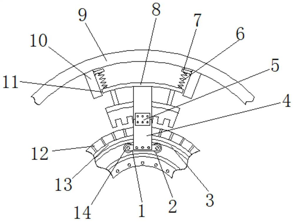
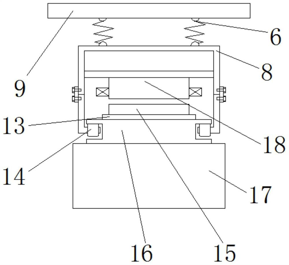
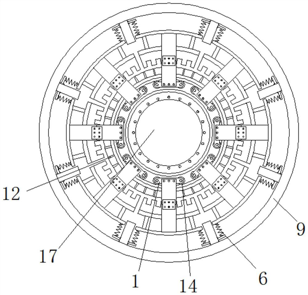
[0023] Describe in detail in conjunction with the accompanying drawings The present invention provides a technical solution: including a tension mechanism, a support frame, a stator power mechanism, a rotor power mechanism, a rotating drum, and a ball mill drum, and it is characterized in that: the stator power mechanism is arra...


PUM


Abstract

The invention discloses a modular permanent magnet direct drive motor used on a ball mill, which comprises a tension mechanism, a supporting frame, a stator power mechanism, a rotor power mechanism, a rotary drum and a ball mill roller, wherein the stator power mechanism is arranged on the centripetal inner side of the supporting frame, the stator power mechanism comprises a stator shell, a stator iron core, a coil and rollers, the stator core is arranged in the stator shell, the tension mechanism is arranged between the stator shell and the supporting frame, the rollers are fixed to the two sides of the stator shell, the rotor power mechanism comprises a rotor core, a permanent magnet and a magnetic isolation aluminum plate and is arranged on the outer surface of the rotary drum, the ball mill roller is arranged on the inner surface of the rotary drum, the rotary drum is provided with a sliding way on which the rollers roll, the rollers are attached to the surface, which is away from the circle center, of the sliding way in the rotary drum. The structure design is novel, the gap between the stator core and the rotor core can be ensured to be constant, the gap can be designed to be very small, the number of permanent magnets is reduced, meanwhile, the influence caused by motor eccentricity is greatly reduced, a protection mechanism is arranged to avoid the phenomenon of chamber sweeping and further damage to the motor, the manufacturing cost is low, mounting and dismounting are convenient, and the problems in the background technology can be effectively solved.

Description

technical field [0001] The invention relates to the technical field of drive motors on ball mills, in particular to a modular permanent magnet direct drive motor used on ball mills. Background technique [0002] The ball mill is a kind of equipment for crushing materials. Its basic principle is to use the rotating force to lift the steel balls in the cylinder to a certain height and drop them on the materials. The materials are crushed by the mutual contact between the steel balls and the materials. The traditional ball mill needs to be equipped with a cumbersome transmission mechanism. In the traditional ball mill, the output shaft of the motor drives the pinion through the reducer, and the pinion drives the large gear to drive the rotation of the drum. Due to the large diameter of the ball mill drum, the drum is used as a permanent magnet direct drive motor. Rotor, in mechanical manufacturing, material processing and assembly will cause the deformation of the drum, the bal...

Claims


Application Information

Patent Timeline
Patent Type & Authority Applications(China)
IPC IPC(8): H02K21/02H02K21/14B02C17/24
CPCH02K21/021H02K21/14B02C17/24H02K2201/03
Inventor 张炳义尚勤贵冯桂宏王帅卞浩田吴鹏尚金铎高敏陈高敏尚金鸽
Owner 河南全新机电设备有限公司
Why Eureka
Try Eureka