
Buck-boost circuit and voltage stress control method

A voltage-boosting and circuit technology, which is applied in the direction of control/regulation systems, electrical components, and adjustment of electrical variables, can solve problems such as short-term CCM mode, excessive voltage stress, and circuit instability, so as to improve reliability and reduce voltage Stress problems, the effect of improving circuit reliability

Pending Publication Date: 2022-01-14
HUAWEI TECH CO LTD
View PDF0 Cites 0 Cited by
  • Summary
  • Abstract
  • Description
  • Claims
  • Application Information

AI Technical Summary

Problems solved by technology

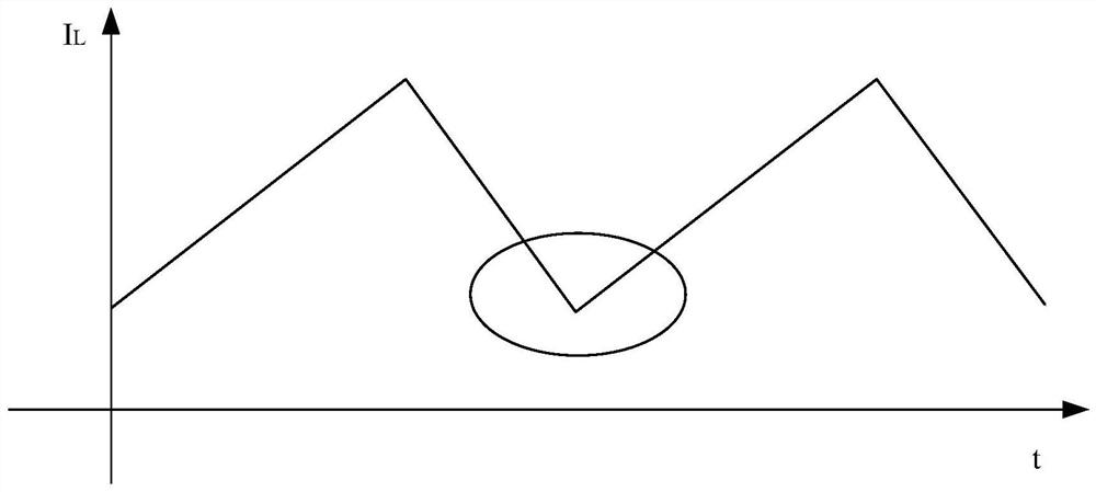
However, when the load jumps, the current flowing through the inductor increases, so the BUCK-BOOST circuit is in a short-term CCM mode, so that the body diode of the freewheeling tube undergoes reverse recovery and the voltage stress exceeds the standard, making the circuit unstable

Method used


Image

  • Buck-boost circuit and voltage stress control method
  • Buck-boost circuit and voltage stress control method
  • Buck-boost circuit and voltage stress control method

Examples


Embodiment Construction

[0040] The embodiments of the present application will be described below with reference to the drawings in the embodiments of the present application. The terms "first", "second", "third" and "fourth" in the specification and claims of the present application and the drawings are used to distinguish different objects, rather than to describe a specific order . Furthermore, the terms "include" and "have", as well as any variations thereof, are intended to cover a non-exclusive inclusion. For example, a process, method, system, product or device comprising a series of steps or units is not limited to the listed steps or units, but optionally also includes unlisted steps or units, or optionally further includes For other steps or units inherent in these processes, methods, products or apparatuses. Reference herein to an "embodiment" means that a particular feature, structure, or characteristic described in connection with the embodiment can be included in at least one embodime...


PUM


Abstract

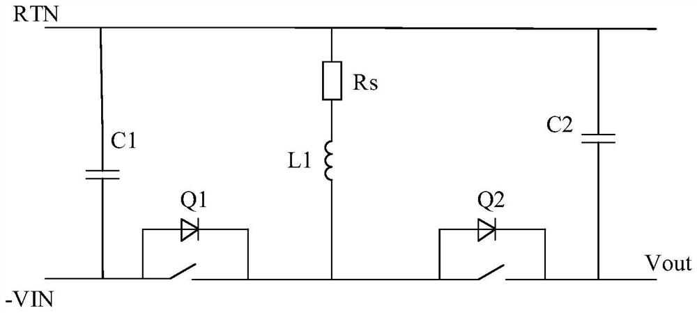
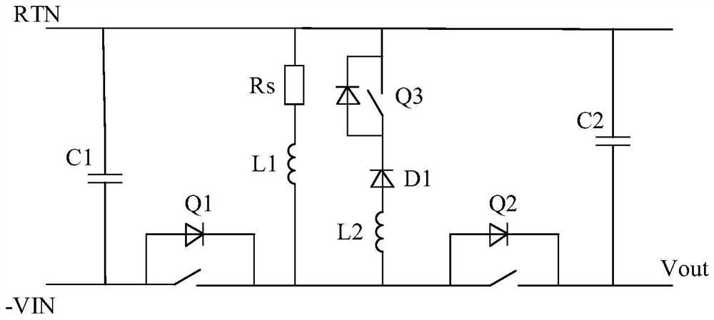
The invention relates to a buck-boost circuit and a voltage stress control method, the buck-boost circuit comprises a logic control circuit, a first switch tube, a second switch tube, an inductor, a resistor, a first capacitor and a second capacitor, the input end of the logic control circuit couples the two ends of the resistor respectively, the output end of the logic control circuit is coupled with the first end of the first switch tube and the first end of the second switch tube, the first end of the resistor is coupled with the first end of the first capacitor and the first end of the second capacitor, and the second end of the resistor is coupled with the first end of the inductor. The second end of the inductor is coupled with the second end of the first switch tube and the second end of the second switch tube, the third end of the first switch tube is coupled with the second end of the first capacitor, and the third end of the second switch tube is coupled with the second end of the second capacitor; and the logic control circuit is used for reducing the switching frequency of the first switch tube and the second switch tube to a first frequency range or a second frequency range under the condition that the current value is greater than a first threshold value. According to the embodiment of the invention, the circuit voltage stress can be reduced.

Description

technical field [0001] Embodiments of the present invention relate to the technical field of electronic circuits, in particular to a buck-boost circuit and a voltage stress control method. Background technique [0002] The buck-boost circuit is an important part of the distributed power supply of wireless communication equipment and low-power module power supply. The BUCK-BOOST circuit has three working modes: continuous conduction mode (continuousconductionmode, CCM), critical conduction mode (boundaryconductionmode, BCM) and discontinuous conductionmode (discontinuousconductionmode, DCM). When the BUCK-BOOST circuit is in CCM mode, because there is a body diode between the source and drain of the MOS tube, there will be a reverse recovery problem of the body diode of the freewheeling tube. When the BUCK-BOOST circuit is in the BCM mode, the rectifier can be turned on with zero voltage to avoid the reverse recovery problem of the diode of the freewheeling tube. [0003] F...

Claims


Application Information

Patent Timeline
Patent Type & Authority Applications(China)
IPC IPC(8): H02M3/158H02M1/088
CPCH02M3/1582H02M1/088
Inventor 叶慈凯张沛然梁宏风王宁
Owner HUAWEI TECH CO LTD
Learn More