Dust removal type generator based on waste heat recycling technology of iron and steel enterprises
A waste heat recovery and generator technology, which is applied in the separation of dispersed particles, chemical instruments and methods, and filtration of dispersed particles, can solve the problem of high-temperature flue gas containing a large amount, and achieve the effect of easy discharge
- Summary
- Abstract
- Description
- Claims
- Application Information
AI Technical Summary
Problems solved by technology
Method used
Image
Examples
Embodiment 1
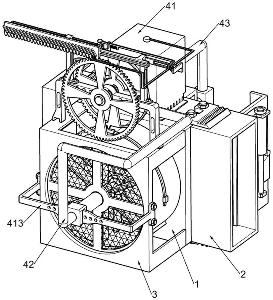
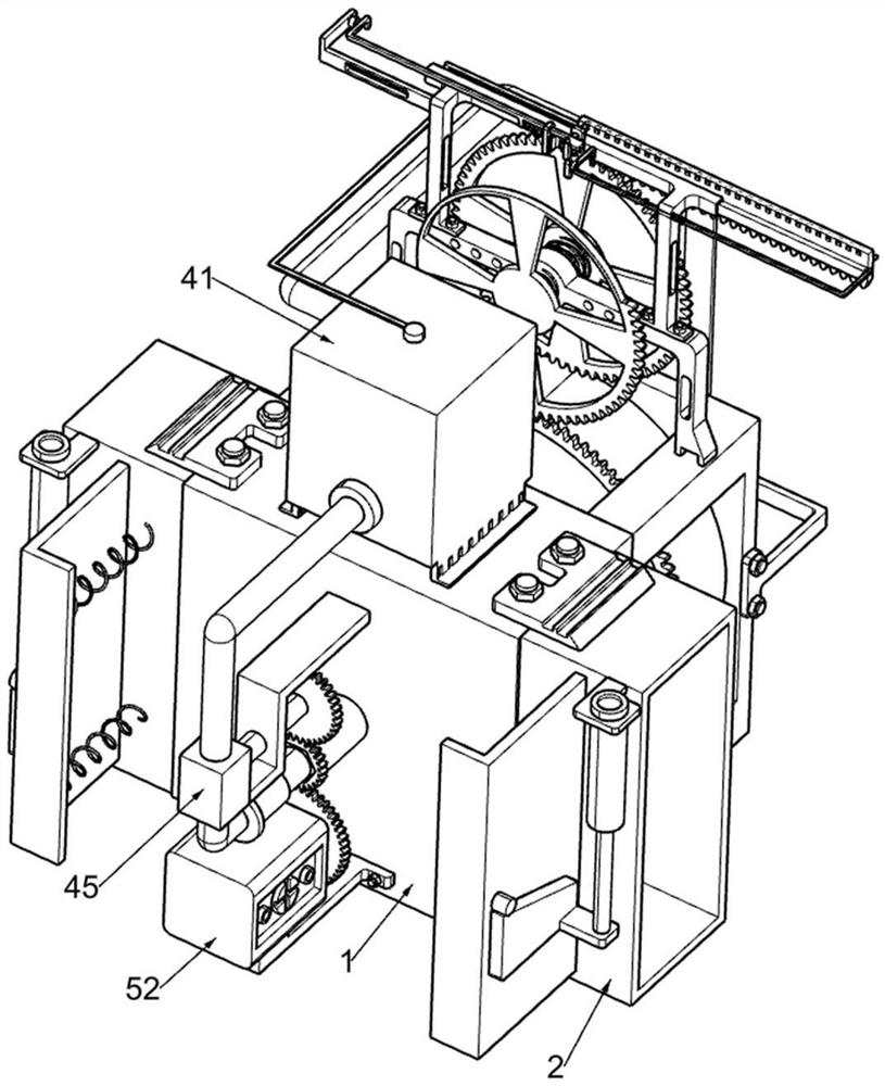
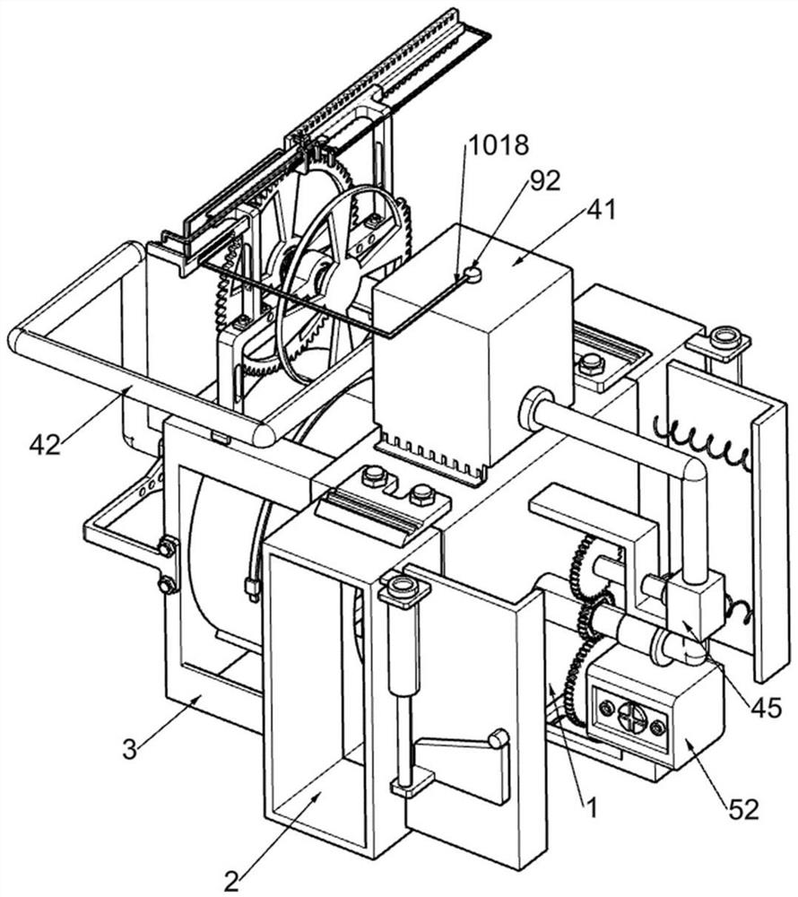
[0046] A dust removal generator based on waste heat recovery and utilization technology of iron and steel enterprises, such as Figure 1-9 As shown, it includes air guide frame 1, air intake frame 2, filter screen 3, exhaust gas cooling part 4, power generation part 5, guide sleeve 6, arc rod with rack 7 and arc baffle plate 8, air guide frame 1 The upper symmetry is connected with the air intake frame 2 for inputting high-temperature flue gas into the air guide frame 1 through bolts, and the outer wall of the air guide frame 1 is connected with a filter screen 3 for filtering the high-temperature flue gas and then discharged. There is an exhaust gas cooling part 4 for cooling the high-temperature flue gas, the gas guide frame 1 is provided with a power generation part 5 for power generation, the filter screen 3 is connected with a guide sleeve 6, and the guide sleeve 6 is slidably connected with a rack arc Shaped bar 7, the band rack arc bar 7 adopts an arc structure, and the...
Embodiment 2
[0051] On the basis of Example 1, such as Figure 10-11 As shown, a heat loss component 9 is also included, and the heat loss component 9 for dissipating heat energy in the cooling liquid is arranged inside the evaporation box 41. The heat loss component 9 includes a first return frame 91, a movable cover plate 92 and The second back-shaped frame 93, the first back-shaped frame 91 is connected inside the evaporation box 41, the first back-shaped frame 91 adopts a back-shaped structure, and the evaporator 41 is slidably connected with a movable cover plate 92, and the lower part of the movable cover plate 92 is Rectangular structure, the movable cover plate 92 is in contact with the first back-shaped frame 91 , and the second back-shaped frame 93 is connected inside the evaporation box 41 .
[0052] During the cooling process, the temperature of the coolant inside the evaporator 41 will increase. When the coolant inside the evaporator 41 rises to a certain value, the high-tempe...
Embodiment 3
[0054] On the basis of Example 2, such as Figure 12-18 Shown, also comprise intermittent driving part 10, and intermittent driving part 10 is located on filter screen 3, and intermittent driving part 10 comprises support seat 101, guide seat 102, second transmission shaft 103, overrunning clutch 104, driving gear 105, First torsion spring 106, sector gear 107, second torsion spring 108, movable plate with oblique bar opening 109, support 1010, limit bar 1011, limit spring 1012, spread bar 1013, return spring 1014, movable bar 1015, magnet adsorption seat 1016, tension spring 1017, special-shaped connecting rod 1018 and push bar 1019, filter screen 3 top is connected with support seat 101, and support seat 101 adopts N type, is connected with guide seat 102 by bolt on the support seat 101, The supporting base 101 is connected with the second transmission shaft 103 in a rotational manner, and the second transmission shaft 103 is connected with an overrunning clutch 104, and the...
PUM
 Abstract
Description
Claims
Application Information
 - R&D
- Intellectual Property
- Life Sciences
- Materials
- Tech Scout
- Unparalleled Data Quality
- Higher Quality Content
- 60% Fewer Hallucinations
Browse by: Latest US Patents, China's latest patents, Technical Efficacy Thesaurus, Application Domain, Technology Topic, Popular Technical Reports.
© 2025 PatSnap. All rights reserved.Legal|Privacy policy|Modern Slavery Act Transparency Statement|Sitemap|About US| Contact US: help@patsnap.com


