Laser pipe cutting and discharging all-in-one machine

An all-in-one machine and laser technology, applied in the field of pipe fittings processing, can solve the problems affecting the normal use of the slag suction pipe, high production cost, product cutting, etc., and achieve the effect of improving the automation level and production efficiency, reducing labor costs and accurate cutting positions.

Pending Publication Date: 2022-01-21
BAOLONG ANHUI AUTO PARTS
View PDF15 Cites 1 Cited by
  • Summary
  • Abstract
  • Description
  • Claims
  • Application Information

AI Technical Summary

Problems solved by technology

[0002] Compared with the original wire cutting equipment and sawing machine, the laser cutting machine can significantly improve the production efficiency when used for round pipe cutting. For example, an online high-efficiency laser pipe cutting device for a pipe drawing machine disclosed in the utility model patent with the notification number CN213969557U is now available. The pipe cutting machine in the prior art mainly uses the rotary chuck to realize the axial conveying and rotation of the pipe. However, since the pipe cutting machine cannot directly and completely cut off the product, it is necessary for the staff to manually tear the cut pipe section from the pipe for processing. In addition, when cutting pipes, it is generally necessary to use a slag suction pipe to suck away the waste slag. However, high-temperature waste slag is very easy to accumulate at the feed port of the slag suction pipe, which affects the normal use of the slag suction pipe. At this time, it is also necessary to manually dredge the suction pipe. Slag pipe, which leads to each laser cutting machine in the prior art must be equipped with at least one operator, resulting in higher production costs

Method used


Image

  • Laser pipe cutting and discharging all-in-one machine
  • Laser pipe cutting and discharging all-in-one machine
  • Laser pipe cutting and discharging all-in-one machine

Examples


Embodiment Construction

[0021] In order to make the purpose, technical solutions and advantages of the present invention clearer, the technical solutions of the present invention are clearly and completely described below in conjunction with specific embodiments and with reference to the accompanying drawings. Obviously, the described embodiments are part of the implementation of the present invention. example, not all examples. Based on the embodiments of the present invention, all other embodiments obtained by persons of ordinary skill in the art without creative efforts fall within the protection scope of the present invention.

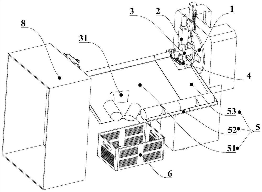
[0022] Such as figure 1 As shown, this embodiment provides a laser tube cutting and blanking integrated machine, including a feeding chuck 1 and a laser head 2 perpendicular to the feeding direction of the feeding chuck 1, and the feeding chuck 1 drives the pipe 3 along the axial direction The movement is cut by the laser emitted by the laser head 2 to form a pipe sectio...


PUM


Abstract

The invention provides a laser pipe cutting and discharging all-in-one machine. The laser pipe cutting and discharging all-in-one machine comprises a feeding chuck and a laser head perpendicular to the feeding direction of the feeding chuck, wherein a pulling-off unit capable of clamping and fixing a cut pipe section is arranged below the laser head, a material collecting unit is arranged below the pulling-off unit, and the pipe section can move on the material collecting unit to enter a material collecting frame. The laser pipe cutting and discharging all-in-one machine has the advantages that the cut pipe section is pulled off and taken down from a pipe through the pulling-off unit, then the cut pipe section is automatically released to the material collecting unit and can automatically enter the material collecting frame, and therefore manual operation is not needed, dependence on the manual operation is avoided, the labor cost is reduced, and the automation level and the production efficiency are improved.

Description

technical field [0001] The invention relates to the technical field of pipe fitting processing, in particular to a laser pipe cutting and blanking integrated machine. Background technique [0002] Compared with the original wire cutting equipment and sawing machine, the laser cutting machine can significantly improve the production efficiency when used for round pipe cutting. For example, an online high-efficiency laser pipe cutting device for a pipe drawing machine disclosed in the utility model patent with the notification number CN213969557U is now available. The pipe cutting machine in the prior art mainly uses the rotary chuck to realize the axial conveying and rotation of the pipe. However, since the pipe cutting machine cannot directly and completely cut off the product, it is necessary for the staff to manually tear the cut pipe section from the pipe for processing. In addition, when cutting pipes, it is generally necessary to use a slag suction pipe to suck away the...

Claims


Application Information

Patent Timeline
Patent Type & Authority Applications(China)
IPC IPC(8): B23K26/00B23K26/142B23K26/38B23K26/70
CPCB23K26/38B23K26/702B23K26/0093B23K26/142
Inventor 方昭柯连运徐睿杨瀚辰戴慧君匡芹
Owner BAOLONG ANHUI AUTO PARTS
Why Eureka
Try Eureka