Supercharge Your Innovation With Domain-Expert AI Agents!

Combined weft yarn spray pipe and manufacturing method thereof

A manufacturing method and combined technology, which is applied in the direction of material gluing, textiles and papermaking, looms, etc., can solve the problems of not being able to adapt to the transformation of air-jet looms, affecting the weft yarn handling force, and low processing efficiency, so as to achieve bonding effect and Good sealing, easy to popularize and use, and high processing efficiency

Active Publication Date: 2022-01-21
WUJIANG XINGYE TEXTILE CO LTD
View PDF6 Cites 0 Cited by
  • Summary
  • Abstract
  • Description
  • Claims
  • Application Information

AI Technical Summary

Problems solved by technology

[0002] The weft yarn nozzle is an important part of the air-jet loom to transport the weft yarn. Its length and internal structure will seriously affect the weft yarn handling force. Improve the carrying force of the weft yarn, such as the Chinese patent CN1548596A discloses such a weft yarn nozzle, and discloses that the longer the length of the weft yarn nozzle, the higher the handling force, but when the tube is made, due to the small diameter of the tube, the length of the tube Large, with a taper in the inner hole, it needs to be processed by special methods such as hot drawing, the processing efficiency is low, and the cost is high. There is also a tapered cavity in the nozzle body to form a Rafal effect, and a long straight tube is connected externally as a weft yarn The way of the nozzle, but this way needs to change the original structure of the nozzle body, which cannot adapt to the transformation of the existing air-jet loom

Method used


Image

  • Combined weft yarn spray pipe and manufacturing method thereof
  • Combined weft yarn spray pipe and manufacturing method thereof
  • Combined weft yarn spray pipe and manufacturing method thereof

Examples


Embodiment Construction

[0025] The preferred embodiments of the present invention will be described in detail below in conjunction with the accompanying drawings, so that the advantages and features of the present invention can be more easily understood by those skilled in the art, so as to define the protection scope of the present invention more clearly.

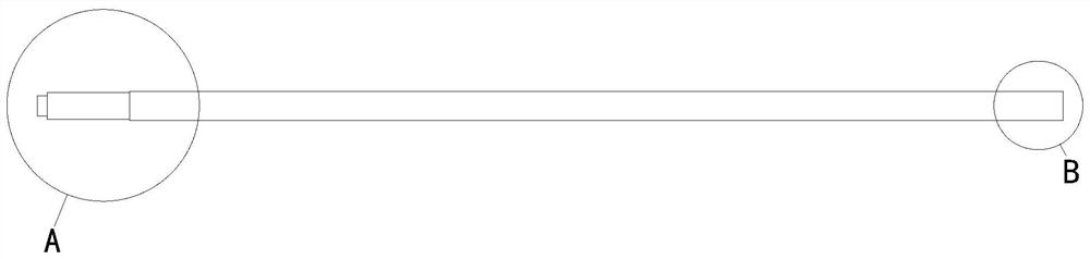
[0026] The left-right direction described in the present invention refers to figure 1 in the left-right direction.

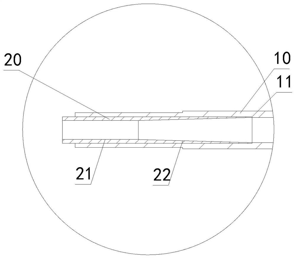
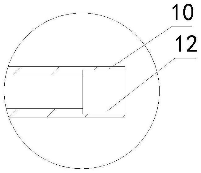
[0027] Such as Figure 1-3 As shown, the combined weft yarn nozzle provided by the present invention includes an outer tube 10 and an inner tube 20 arranged coaxially, the length of the outer tube 10 is at least 5 times that of the inner tube 20, the outer tube 10 is a straight tube, and the inner tube 20 is embedded Set at the end of the outer tube 10 close to the nozzle, the weft yarn passes through the inner tube 20 and the outer tube 10 from left to right in sequence, the outer wall of the inner tube 20 and the inner wall of t...


PUM

PropertyMeasurementUnit
Wall thicknessaaaaaaaaaa
Lengthaaaaaaaaaa
Wall thicknessaaaaaaaaaa

Abstract

The invention provides a combined weft yarn spray pipe. The combined weft yarn spray pipe comprises an outer pipe and an inner pipe which are coaxially arranged, the outer pipe is a straight pipe, the inner pipe is embedded in the end, close to a nozzle, of the outer pipe, the outer wall of the inner pipe and the inner wall of the outer pipe are connected through glue, and the inner wall of the inner pipe comprises a cylindrical face with the inner diameter smaller than that of the outer pipe and a conical surface with the small end connected with the cylindrical face. The large head end of the conical surface is in contact with the inner wall of the outer pipe, so that the conical surface forms a transition surface between the cylindrical surface and the inner wall of the outer pipe, the Laval effect can be generated, the split design of the outer pipe and the inner pipe can be utilized, and the machining process is simplified; and the technical effects of being simple in structure, convenient to machine, high in machining efficiency, low in cost and suitable for improvement of an existing air jet loom are achieved. According to a manufacturing method, the super glue is smeared on the outer wall of the inner pipe and then rotationally inserted into the outer pipe, the super glue can be distributed in the circumferential direction of the outer wall of the inner pipe, the bonding effect and the sealing performance are good, operation is easy, implementation is easy, and application and popularization are convenient.

Description

technical field [0001] The invention belongs to the technical field of air-jet looms, and in particular relates to a combined weft yarn nozzle and a manufacturing method thereof. Background technique [0002] The weft yarn nozzle is an important part of the air-jet loom to transport the weft yarn. Its length and internal structure will seriously affect the weft yarn handling capacity. Improve the carrying force of the weft yarn, such as the Chinese patent CN1548596A discloses such a weft yarn nozzle, and discloses that the longer the length of the weft yarn nozzle, the higher the handling force, but when the tube is made, due to the small diameter of the tube, the length of the tube Large, with a taper in the inner hole, it needs to be processed by special methods such as hot drawing, the processing efficiency is low, and the cost is high. There is also a tapered cavity in the nozzle body to form a Rafal effect, and a long straight tube is connected externally as a weft yarn...

Claims


Application Information

Patent Timeline
IPC IPC(8): D03D47/30F16B11/00
CPCD03D47/306F16B11/008
Inventor 曹洪兴
Owner WUJIANG XINGYE TEXTILE CO LTD
Features
  • R&D
  • Intellectual Property
  • Life Sciences
  • Materials
  • Tech Scout
  • Unparalleled Data Quality
  • Higher Quality Content
  • 60% Fewer Hallucinations
Learn More