Throttler for air floatation part and air floatation piston comprising throttler

A technology of restrictor and air flotation, applied in air cushion bearings, fluid pressure actuating devices, bearings, etc., can solve the problems of easy blockage and inconsistent throttling flow of the restrictor

Pending Publication Date: 2022-01-21
LIHAN CRYOGENICS
View PDF0 Cites 0 Cited by
  • Summary
  • Abstract
  • Description
  • Claims
  • Application Information

AI Technical Summary

Problems solved by technology

[0005] This application provides a restrictor for air-floating parts and an air-floating piston including the restrictor,

Method used


Image

  • Throttler for air floatation part and air floatation piston comprising throttler
  • Throttler for air floatation part and air floatation piston comprising throttler
  • Throttler for air floatation part and air floatation piston comprising throttler

Examples


Embodiment 1

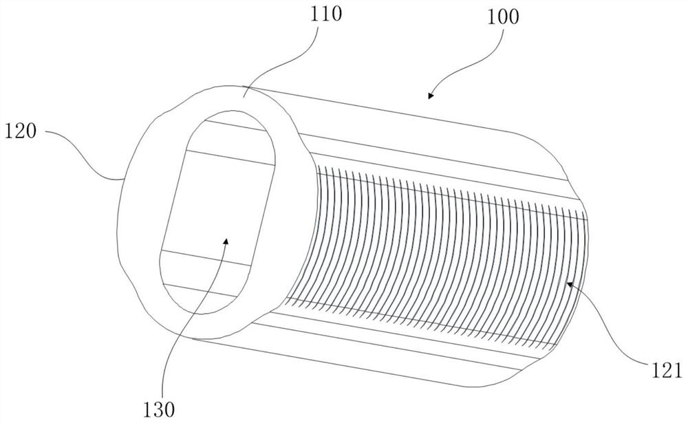
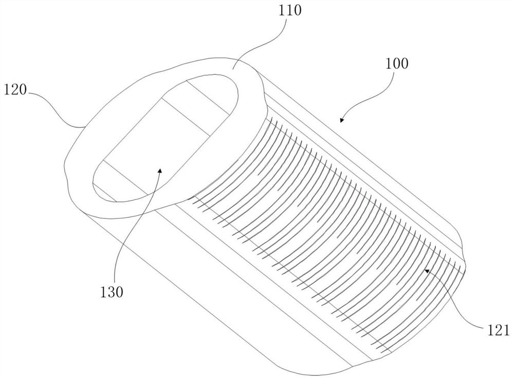
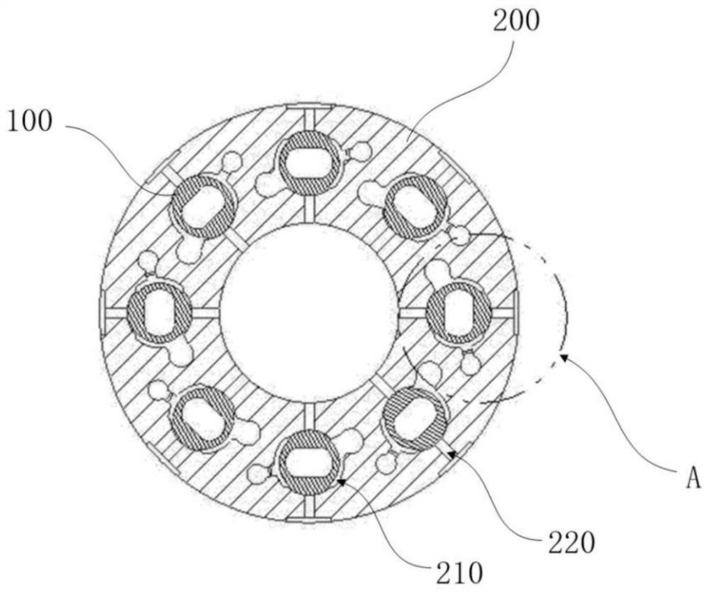
[0048] figure 1 It is a structural schematic diagram of a structure of the restrictor of the present application; figure 2 It is a structural schematic diagram of another structure of the restrictor of the present application; image 3 An assembly drawing of the restrictor and air flotation parts; Figure 4 for image 3 Enlarged image at A.

[0049] Such as Figure 1-4 As shown, the present embodiment provides a restrictor 100 for floating parts, the partial area or the entire area of ​​the outer surface of the restrictor 100 is a rough surface, and the air floating part 200 is provided with a restrictor 100 for installation. The installation cavity 210 and the air outlet hole 220 communicating with the installation cavity 210, the restrictor 100 is fixedly connected to the air outlet hole 220 in the installation cavity 210 through an interference fit connection, and part of the rough surface of the restrictor 100 faces the air outlet hole 220 , after the gas enters the in...

Embodiment 2

[0068] Figure 5 is a schematic diagram of the structure of the air-floating piston; Figure 6 is the side view of the air piston; Figure 7 for Figure 6 Sectional view of B-B direction; Figure 8 for Figure 7 The magnified image at C in the center; Figure 9 It is a schematic diagram of the structure of the piston and the cylinder.

[0069] Such as Figure 5-8 As shown, this embodiment provides an air-floating piston 300, which includes the restrictor 100 as described in the technical solution of Renyi in Embodiment 1, and the air-floating piston 300 in this embodiment is the embodiment The air-floating component 200 described in 1, the air-floating component 200 in this embodiment has the following features in addition to the features of the air-floating component 200 described in Embodiment 1.

[0070] Specifically, the air-floating piston 300 of this specific embodiment includes a piston body 330, the piston body 330 is a circular cylindrical structure, the installa...


PUM


Abstract

The invention provides a throttler for an air floatation part and an air floatation piston comprising the throttler. The air floatation part is provided with a mounting cavity for mounting the throttler and an air outlet hole which communicates with the mounting cavity; the local area or the whole area of the outer side face of the throttler is a rough surface, the throttler is fixedly connected to the air outlet hole in the mounting cavity in an interference fit connection mode, part of the rough surface of the throttler faces the air outlet hole, after air enter into the mounting cavity, and the air makes contact with the rough surface and flows into the air outlet hole through the rough surface to achieve gas throttling. Compared with single small hole throttling, the throttler has the advantages that the risk of dirt dust particle blockage can be reduced, the throttling reliability is improved, throttling is achieved through the rough surface, machining is easy, large-batch production and installation are convenient, and the cost is low.

Description

technical field [0001] The present application relates to the technical field of air-floating pistons, in particular to a restrictor for air-floating components and an air-floating piston including the restrictor. Background technique [0002] With the increasing application of gas lubricants, more and more attention has been paid to the research on air bearings, air bearings, pistons and other air bearings. Both the air-floating piston and the air-bearing bearing use a throttle to realize gas throttling and increase the gas flow rate, and then realize the throttling air-floating function of the air-floating piston and air-bearing. [0003] For air bearings, there are two kinds of restrictor structures commonly used, one is a small hole restrictor, and the other is a porous medium restrictor. Wherein, the structure of the small-hole restrictor is as follows: the small-hole restrictor is provided with a gas circulation channel with an open end, and the end of the gas circula...

Claims


Application Information

Patent Timeline
IPC IPC(8): F15B15/14F15B15/20F16C32/06
CPCF15B15/1423F15B15/1447F16C32/0622
Inventor 陈帅李海冰张益炳龙小丹
Owner LIHAN CRYOGENICS
Why Eureka
Try Eureka