Direction of arrival estimation method based on adaptive rotation adjustment of unmanned aerial vehicle
A direction-of-arrival estimation and rotation adjustment technology, which is applied to direction finders using radio waves, directional multi-channel systems using radio waves, etc., can solve problems such as lower bound locking and reduction of the theoretical limit of the mean square error of the angle of arrival estimation. , to achieve the effect of reducing the secondary loss, fitting the motion characteristics of the UAV, and improving the accuracy
- Summary
- Abstract
- Description
- Claims
- Application Information
AI Technical Summary
Problems solved by technology
Method used
Image

Examples
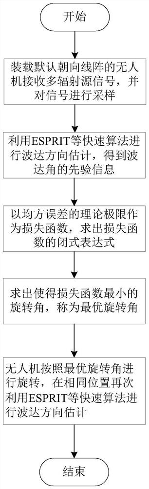
specific Embodiment
[0058] Step S2.1 Obtain the correlation matrix R according to the received signal ZZ =E[x H (txt)];
[0059] to R ZZ Doing the eigenvalue decomposition, R ZZ U=ΛU, where Λ=diag{λ 1 ,...,λ M}, U=[e 1 ,...,e M ] is the feature matrix, e m for lambda m The corresponding eigenvector, λ 1 ≥…≥λ M ;
[0060] Step S2.2, taking the eigenvectors corresponding to the larger K eigenvalues to form a signal subspace, E s =[e 1 ,...,e K ], taking the first M-1 rows and the last M-1 rows to form a matrix E x and E y ;
[0061] Step S2.3, pair matrix Perform eigenvalue decomposition to obtain the characteristic matrix E, and decompose it into K×K sub-matrices:
[0062]
[0063] Step S2.4, calculation The eigenvalue λ of k ;
[0064] Step S2.5, for Perform eigenvalue decomposition to obtain the prior value of the angle of arrival as follows:
[0065]
[0066] Step S3. Obtain the loss function based on the mean value of the diagonal elements of the Cramer-Rao bo...
PUM
 Abstract
Description
Claims
Application Information