
Active heat reduction design method for aircraft rudder shaft gap thermal environment

An aircraft rudder and design method technology, applied in computer-aided design, design optimization/simulation, calculation, etc., can solve the problems of affecting the deflection of the rudder surface, increasing the risk of collision between the rudder and the installation surface, and limited, so as to reduce the mass flow, reduce the Influence, effect of thermal environment reduction

Pending Publication Date: 2022-01-21
AERODYNAMICS NAT KEY LAB
View PDF0 Cites 2 Cited by
  • Summary
  • Abstract
  • Description
  • Claims
  • Application Information

AI Technical Summary

Problems solved by technology

[0003] The traditional thermal environment design method of the rudder shaft gap is realized by reducing the gap height. On the one hand, reducing the gap height is very limited to alleviate the local thermal environment of the gap. On the other hand, reducing the gap height will increase the collision between the rudder and the mounting surface. risk, thereby affecting the deflection of the rudder surface
Therefore, the traditional thermal environment design method of the rudder shaft gap is difficult to meet the needs of thermal protection of the rudder shaft at the present stage.

Method used


Image

  • Active heat reduction design method for aircraft rudder shaft gap thermal environment
  • Active heat reduction design method for aircraft rudder shaft gap thermal environment
  • Active heat reduction design method for aircraft rudder shaft gap thermal environment

Examples


Embodiment Construction

[0048] In order to make the purpose, technical solutions and advantages of the embodiments of the present invention clearer, the technical solutions in the embodiments of the present invention will be clearly and completely described below in conjunction with the drawings in the embodiments of the present invention. Obviously, the described embodiments It is a part of embodiments of the present invention, but not all embodiments. The components of the embodiments of the invention generally described and illustrated in the figures herein may be arranged and designed in a variety of different configurations.

[0049] Accordingly, the following detailed description of the embodiments of the invention provided in the accompanying drawings is not intended to limit the scope of the claimed invention, but merely represents selected embodiments of the invention. Based on the embodiments of the present invention, all other embodiments obtained by persons of ordinary skill in the art wi...


PUM


Abstract

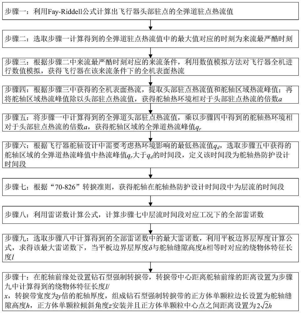
The invention discloses an active heat reduction design method for an aircraft rudder shaft gap thermal environment, which comprises the following steps: calculating a heat flow value of a head stationary point, selecting the most harsh moment of incoming flow to carry out thermal environment numerical simulation on a whole aircraft, and obtaining a multiple relationship between a rudder shaft gap local heat flow peak value and an aircraft head heat flow peak value; acquiring the change condition of a rudder shaft gap local heat flow peak value along a trajectory by the multiple relation, determining a time period in which rudder shaft thermal protection design needs to be carried out according to the change condition, determining a laminar flow time period in the time period by a transition criterion, calculating the maximum Reynolds number in the laminar flow time period, and calculating the maximum Reynolds number under the maximum Reynolds number. When the thickness of the boundary layer is 1 / x of the height of the rudder shaft gap, the corresponding object-surrounding characteristic length is obtained, and finally, the diamond-shaped forced transition tape is arranged at the position away from the front edge of the rudder by the object-surrounding characteristic length, so that the whole rudder shaft gap is in turbulent flow under the working condition that the thermal environment is relatively harsh, and the thermal environment heat flow peak value of the rudder shaft gap is greatly reduced.

Description

technical field [0001] The invention relates to the field of numerical simulation of the aerodynamic thermal environment, in particular to an active heat reduction design method for the thermal environment of the rudder shaft gap of an aircraft. Background technique [0002] Hypersonic aircraft is a key carrier for rapid global strikes, and its military and even economic significance is self-evident. The severe aerodynamic heating that needs to be overcome first in the development of hypersonic vehicles. With the continuous development of hypersonic aircraft technology, the flight time of the aircraft is getting longer, the maneuverability is getting stronger, and the shape is becoming more and more complex, all of which make the heat protection problem more and more serious. Especially for the rudder shaft and rudder shaft gap area of ​​the aircraft, the sudden change of shape causes complex interference flow and local high heat flow area in this area. The peak value of he...

Claims


Application Information

Patent Timeline
Patent Type & Authority Applications(China)
IPC IPC(8): G06F30/15G06F30/17G06F30/20G06F111/10G06F119/08
CPCG06F30/15G06F30/17G06F30/20G06F2111/10G06F2119/08Y02T90/00
Inventor 邱波李强国义军刘深深曾磊张昊元朱言旦刘骁李睿智石友安沈斌贤
Owner AERODYNAMICS NAT KEY LAB
Learn More