
Internal combustion engine

Active Publication Date: 2014-08-05
DAIMLER AG
View PDF25 Cites 2 Cited by
  • Summary
  • Abstract
  • Description
  • Claims
  • Application Information

AI Technical Summary

Benefits of technology

This approach enables compliance with current and future emission limits while maintaining low fuel consumption, specifically by optimizing the compromise between nitrogen oxide and soot emissions through controlled exhaust gas recirculation, resulting in reduced nitrogen oxide emissions and improved fuel efficiency.

Problems solved by technology

These known solutions have problems, however, with regard to reaching future emission limits in particular.

Method used


Image

  • Internal combustion engine
  • Internal combustion engine
  • Internal combustion engine

Examples


Embodiment Construction

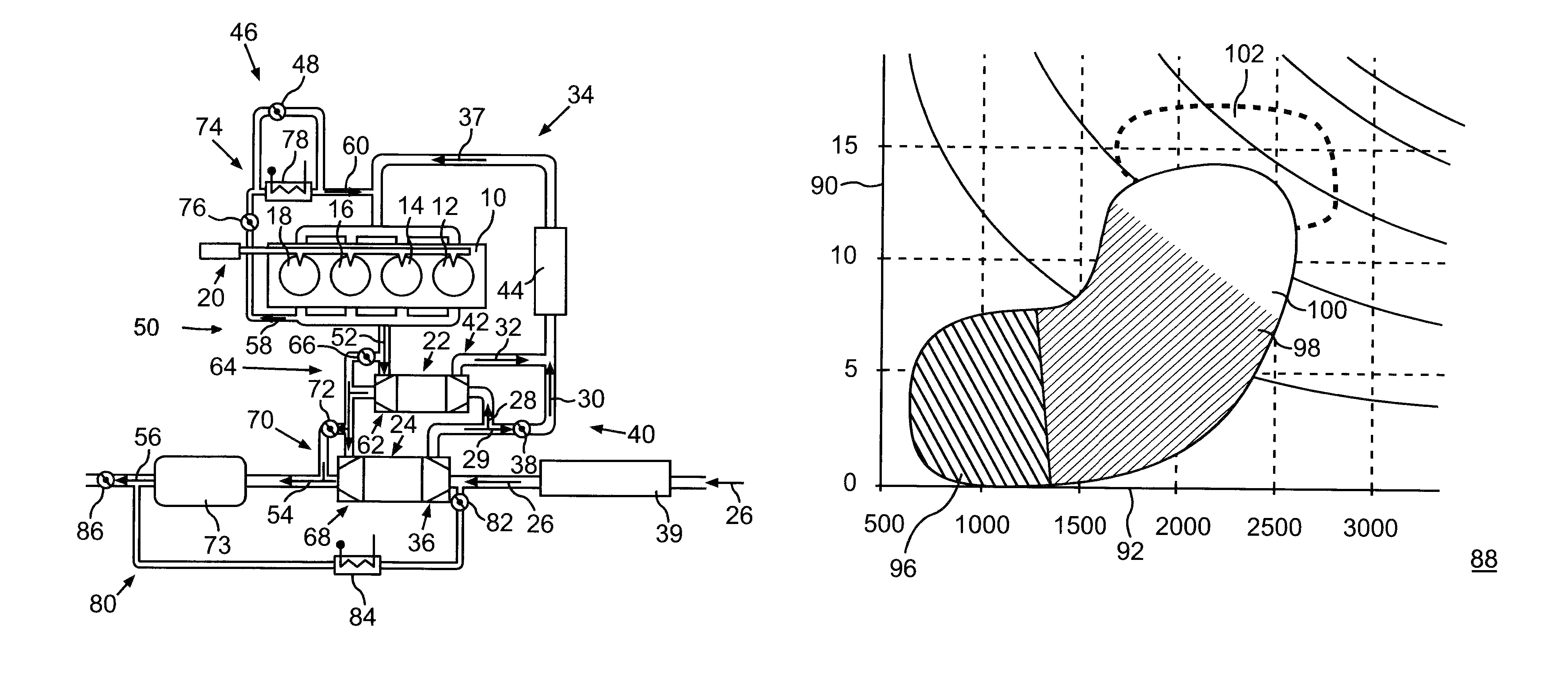
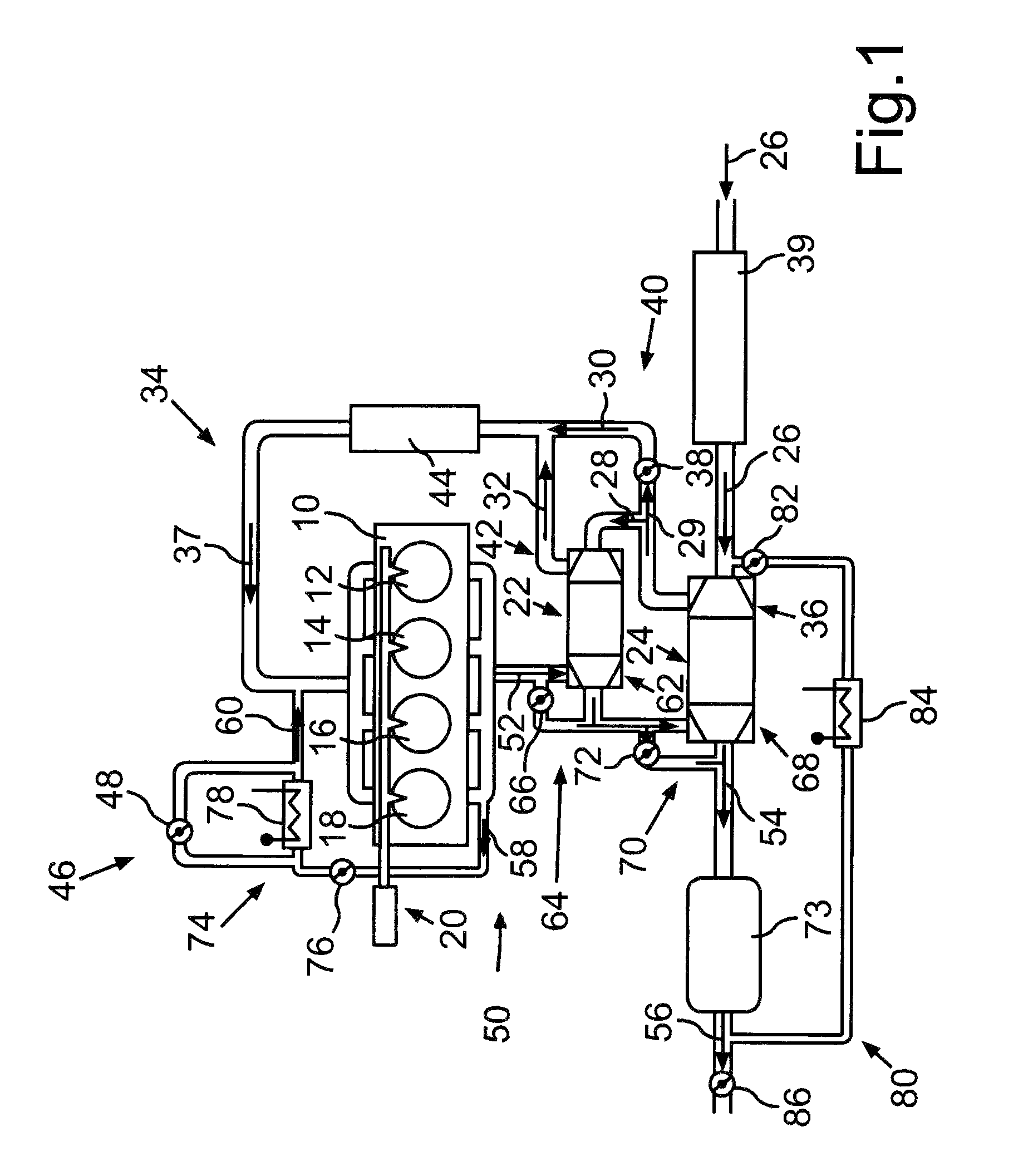
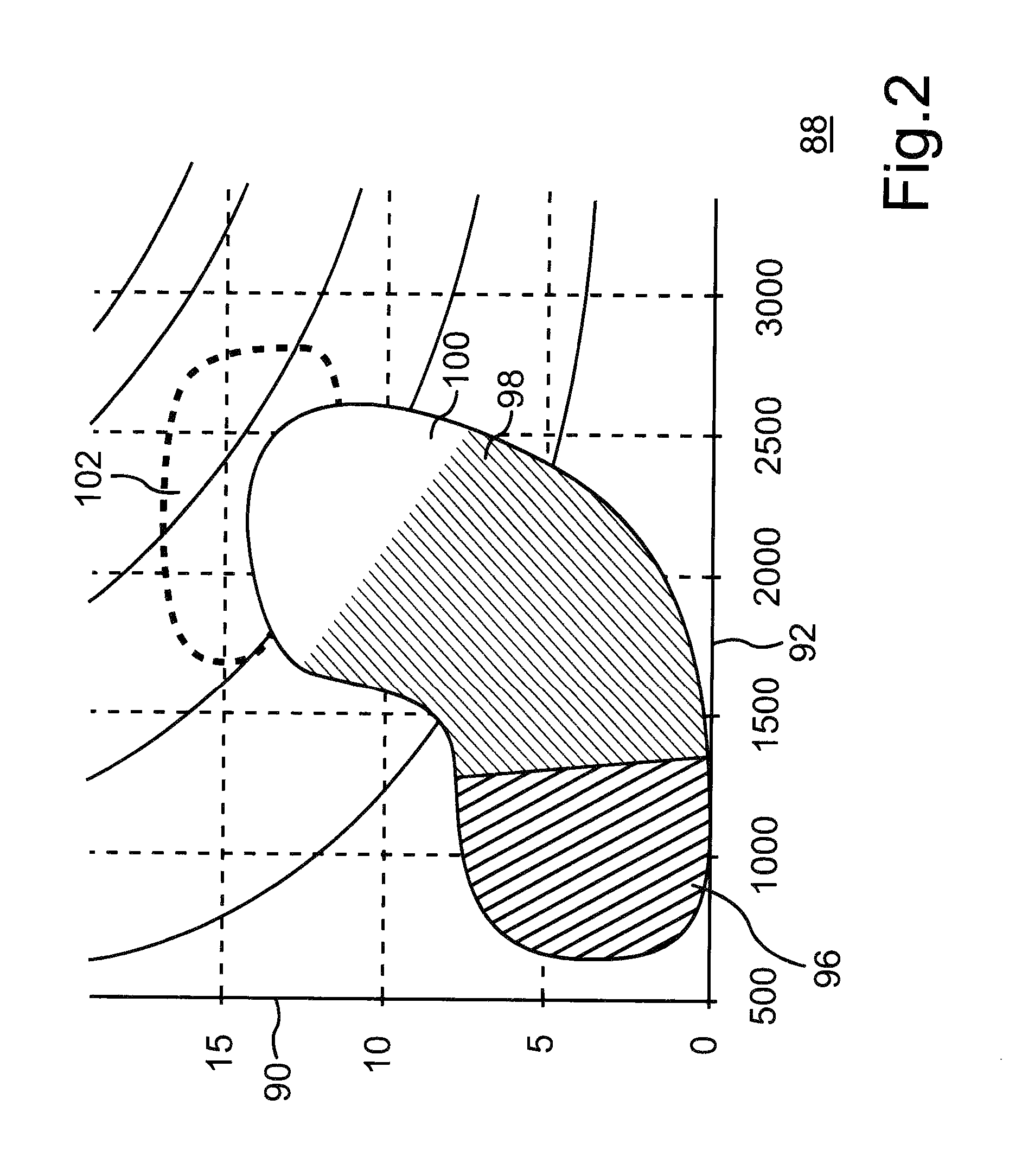
[0029]While FIG. 1 shows schematically an internal combustion engine with a two way exhaust gas recirculation, by which compliance with EU6 emission limits is easily possible, FIGS. 2 to 5 show operating strategies of the internal combustion engine or components of the internal combustion engine and the two way exhaust gas recirculation in order to achieve low emissions and also low fuel consumption.

[0030]FIG. 1 shows an internal combustion engine 10 which is in the form of a diesel engine and comprises four cylinders 12, 14, 16 and 18, into which fuel is injected by a high pressure injection system 20. The internal combustion engine 10 comprises a high pressure exhaust gas turbocharger 22 and a low pressure exhaust gas turbocharger 24 arranged downstream thereof in series. Air drawn in according to direction arrows 26 by the internal combustion engine on an intake side 34 thereof and filtered by an air filter 39 is pre-compressed by a compressor 36 of the low pressure exhaust gas t...


PUM


Abstract

In an internal combustion engine and a method of operation the internal combustion engine which includes a high pressure and a low pressure turbocharger having exhaust gas turbines arranged in series in an engine exhaust line provided with a high pressure exhaust gas recirculation line and a low pressure exhaust gas recirculation line via which exhaust gas can be conducted to an inlet line of the engine, the arrangement is switchable depending on the engine speed between an exhaust gas recirculation by way of the high pressure line and an exhaust gas recirculation by way of both, the high pressure and the low pressure line, to achieve low emissions and low fuel consumption.

Description

[0001]This is a Continuation in Part application of international patent application PCT / EP2010 / 004044 filed Jul. 3, 2010 and claiming the priority of German patent application 10 2009 036 743.8 filed Aug. 8, 2009.[0002]The invention relates to a method for operating an internal combustion engine having at least two turbochargers with turbines arranged in series in the engine exhaust duct and compressors arranged in series in the engine intake duct and with exhaust gas recirculation from the engine exhaust duct to the engine intake duct and also to an internal combustion engine designed to perform the method.[0003]WO 2007 / 107865 A2 discloses an internal combustion engine with at least one exhaust gas turbocharger which comprises on an exhaust gas side of the internal combustion engine a turbine through which an exhaust gas of the internal combustion engine can flow, wherein subject to an operating state of the internal combustion engine by means of a high pressure exhaust gas recirc...

Claims


Application Information

Patent Timeline
Patent Type & Authority Patents(United States)
IPC IPC(8): F02B33/44F01N3/00F01N3/021F01N3/10F01N13/02F02B29/04F02B37/00F02B37/013F02B37/12F02B37/18F02M25/07
CPCF02B37/18F02M25/0732F02M25/0728F01N3/106F02B37/004F02B37/127F02M25/0711F02B37/013F02M25/0744F01N3/103F01N3/021F02B29/0406Y02T10/121Y02T10/144F02M25/0718F01N13/02F01N2240/36F01N13/009F02M26/08F02M26/15F02M26/24F02M26/25F02M26/38F02B37/162Y02T10/12
Inventor BEIL, HEIKOWEGENAST, FLORIAN
Owner DAIMLER AG
Learn More