
An air-cooled structure of an outer rotor permanent magnet motor

A permanent magnet motor, air-cooled structure technology, applied in the magnetic circuit shape/style/structure, electric components, electromechanical devices, etc., can solve the problem of the limited power level of the outer rotor permanent magnet motor, the poor air-cooled heat dissipation capacity, the increase of the motor temperature rise and other problems, to achieve the effect of convenient and fast processing, improved heat dissipation capacity, and increased cooling air flow rate

Active Publication Date: 2022-03-15
承德盛乾特种电机制造有限公司
View PDF8 Cites 0 Cited by
  • Summary
  • Abstract
  • Description
  • Claims
  • Application Information

AI Technical Summary

Problems solved by technology

However, the stator of the outer rotor permanent magnet motor is inside the rotor, and its heat dissipation capability is poor. In order to solve this problem, the outer rotor permanent magnet motor is generally air-cooled or water-cooled. However, for some sites, the use of water cooling not only increases the cost, but also brings Due to disadvantages such as changing the coolant and taking up extra space, air cooling is more convenient, but compared with water cooling, air cooling has poor heat dissipation capacity, which will increase the temperature rise of the motor, and the power level of the air-cooled outer rotor permanent magnet motor is allowed limited

Method used


Image

  • An air-cooled structure of an outer rotor permanent magnet motor
  • An air-cooled structure of an outer rotor permanent magnet motor
  • An air-cooled structure of an outer rotor permanent magnet motor

Examples


Embodiment Construction

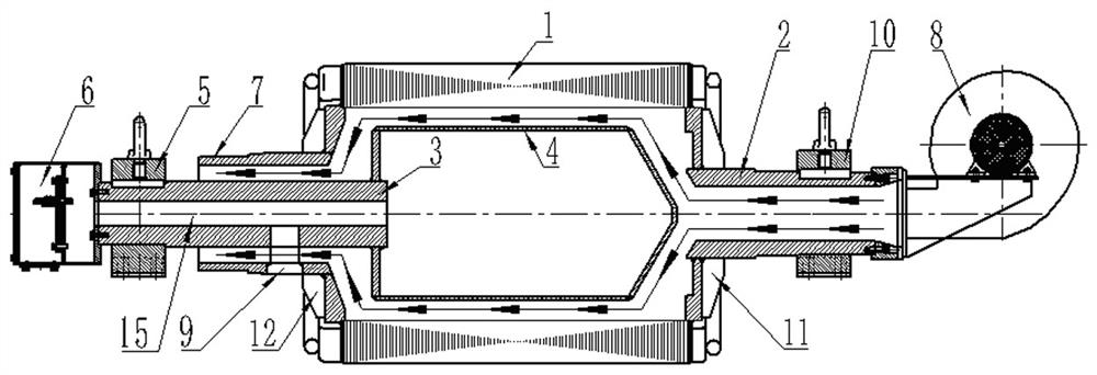
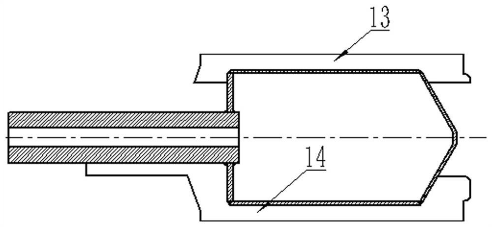
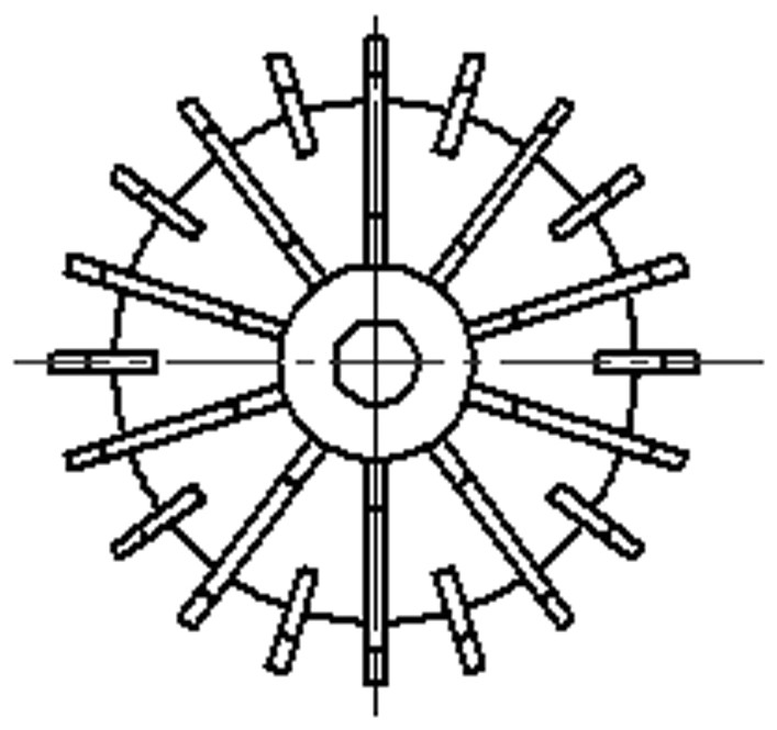
[0022] Such as Figure 1-4 As shown, an air-cooled structure of an outer rotor permanent magnet motor includes a stator core 1, an air inlet side half shaft 2 and an outlet side bearing bracket 7, and the air inlet side half shaft 2 and the outlet side bearing bracket 7 are connected to The two ends of the stator core 1, and the stator core 1, the air inlet side half shaft 2 and the outlet side bearing bracket 7 are connected to form a hollow passage for ventilation, wherein the stator core 1 is 0.5mm thick DW470-50 is laminated, with pressure plates at both ends, and axially fastened by cylindrical pins, windings are arranged in the stator core slot; a cooling fan is installed at the air inlet end of the half shaft 2 on the air inlet side 8. The central through hole of the outlet side bearing bracket 7 is provided with an outlet side half shaft 3, and the central through hole of the stator core 1 is provided with an air duct inner retaining ring 4, and the air duct inner reta...


PUM


Abstract

The invention discloses an air-cooled structure of an outer rotor permanent magnet motor, which comprises a stator core, an air inlet side half shaft and an outlet side bearing bracket, and the wind inlet side half shaft and the outlet side bearing bracket are connected to both ends of the stator iron core , and the three are connected to form a hollow passage for ventilation. A cooling fan is installed at the air inlet end of the half shaft on the air inlet side. There is an inner retaining ring of the air duct, which is connected to the semi-shaft on the outgoing line side. There are multiple air duct baffles on the inner retaining ring of the air duct. One side of the air inlet of the side half shaft is connected on the support seat of the air inlet side. The invention has compact layout, convenient and fast installation, heat exchange between the cooling air and the stator core directly, the design of the air duct baffle increases the heat dissipation area, the inner retaining ring of the air duct increases the flow rate of the cooling air, improves the heat dissipation capacity of the motor, and Increased air cooling power rating.

Description

technical field [0001] The invention relates to the technical field of motors, in particular to an air-cooled structure of an outer rotor permanent magnet motor. Background technique [0002] In the belt conveyor drive system, the traditional belt conveyor drive generally adopts the drive mode of asynchronous motor + hydraulic coupling + reducer + drive roller. The drive chain of the entire drive system is lengthy, which virtually increases useless mechanical friction. It also increases the overall loss of the driving device, and the damage of any one of the components will directly lead to the shutdown of the entire driving device. This traditional drive method has problems such as low transmission efficiency, heavy operation and maintenance workload, and large space required for equipment layout. [0003] In view of the many shortcomings and problems of the traditional electric drum, the outer rotor permanent magnet motor acts as the drum, which simplifies the transmissio...

Claims


Application Information

Patent Timeline
Patent Type & Authority Patents(China)
IPC IPC(8): H02K9/04H02K1/20H02K5/20H02K5/22H02K3/50
CPCH02K9/04H02K1/20H02K5/207H02K5/225H02K3/50H02K2205/09
Inventor 何功飞范玉华翁玉元刘元章姜姗姗
Owner 承德盛乾特种电机制造有限公司
Learn More