

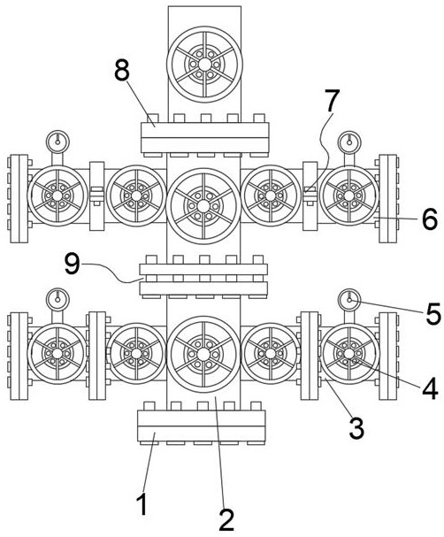
Single-pipe thermal recovery wellhead device
A wellhead device and thermal recovery technology, applied in the wellbore/well valve device, drill pipe, casing, etc., can solve the problem of not having a steering adjustment structure, increasing the operation difficulty of a single-tube thermal recovery wellhead device, and inability to flexibly adjust the single-tube thermal recovery wellhead device. Problems such as the angle of use of the tube thermal recovery wellhead device to achieve the effect of improving flexibility
- Summary
- Abstract
- Description
- Claims
- Application Information
AI Technical Summary
Problems solved by technology
Method used
Image

Examples
Embodiment 1
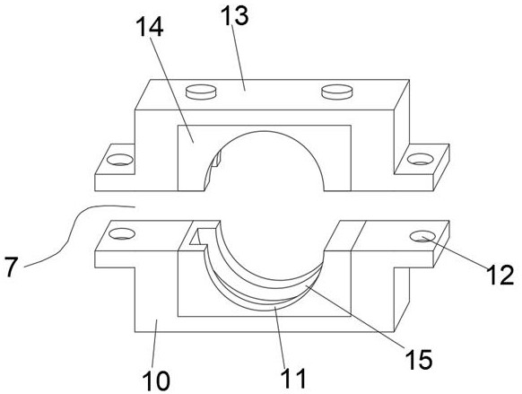
[0035] The fixed clip 7 includes a lower clip cover 10 and an upper clip cover 13, the upper clip cover 13 is fixedly installed on the upper outer surface of the lower clip cover 10, and the sides of the lower clip cover 10 and the upper clip cover 13 are all provided with matching bolts for fixing Fixed lug 12, utilize the setting of fixed lug 12, can cooperate bolt to carry out fixing operation between the lower card cover 10 and the upper card cover 13, avoid falling off between the lower card cover 10 and the upper card cover 13.
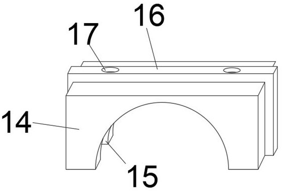
[0036] The inner sides of the lower card cover 10 and the upper card cover 13 are all movably socketed with a combined clamping plate 14 for docking the second branch pipe 6, and the side outer surface of the combined clamping plate 14 is provided with a positioning clamping strip 16 for docking. Threaded holes 17 for fixing are provided through the bar 16, and the combined clamping plate 14 can be stuck on the inside of the lower clamping cover 10...
Embodiment 2
[0040] The middle part of the upper fixed disc 21 is fixedly equipped with an outer sleeve 20, and the upper middle part of the lower fixed disc 18 is fixedly equipped with an inner sleeve 19. When the upper fixed disc 21 and the lower fixed disc 18 are installed, the inner sleeve 19 and the inner sleeve The pipes 19 are butted, and the upper fixed disk 21 is rotated, so that the first branch pipe 3 completes the rotation adjustment.
[0041] The outer surface of the side of the inner casing 19 is fixedly installed with a limit snap ring, and the inner sides of the upper fixed disk 21 and the lower fixed disk 18 are provided with several groups of through holes for use with the lock bolts. When the outer casing 20 and the inner casing 19 are docked , the lower part of the outer sleeve 20 can be fixed by using the limit snap ring, and at the same time, inserting bolts in the through holes of the upper fixed plate 21 and the lower fixed plate 18 can fix the rotated outer tube 20 ...
PUM
 Abstract
Description
Claims
Application Information