Cable-free paraffin removal robot
A robot and wax removal technology, applied in cleaning equipment, wellbore/well parts, buildings, etc., can solve the problems of high cost, polluting the environment, manual operation, etc., and achieve high work efficiency
- Summary
- Abstract
- Description
- Claims
- Application Information
AI Technical Summary
Problems solved by technology
Method used
Image

Examples
Embodiment Construction
[0041] Below in conjunction with each accompanying drawing, the present invention is described in detail.
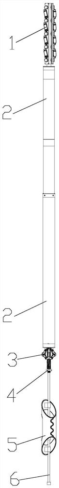
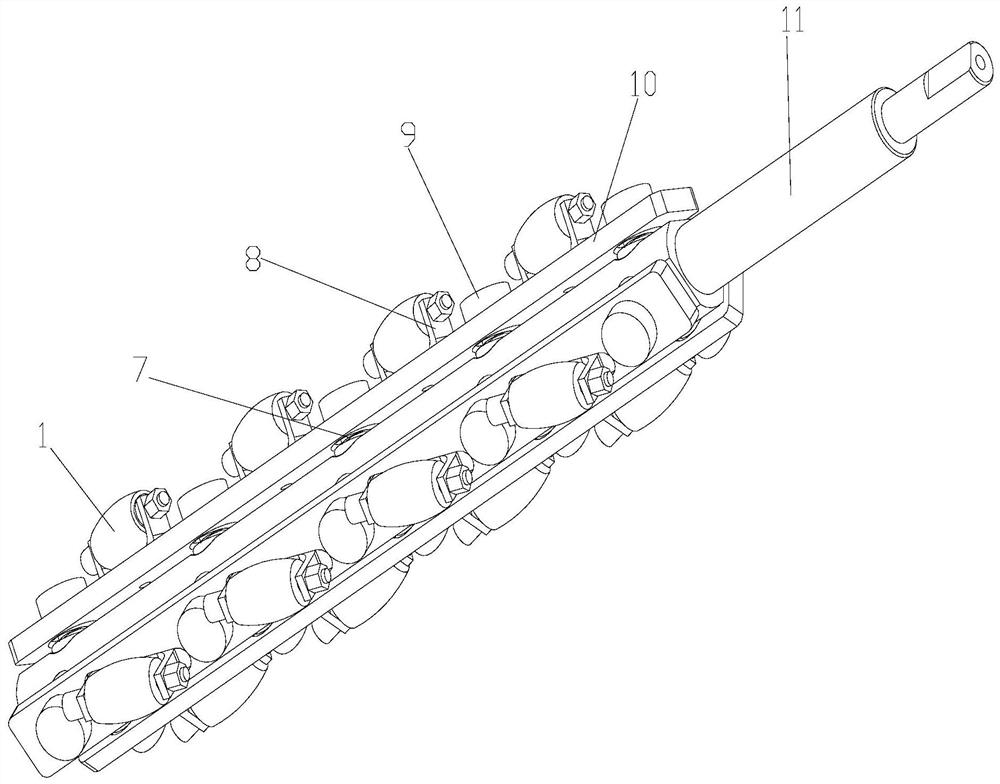
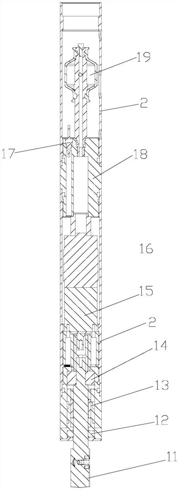
[0042] as attached figure 1 , 2 , 3, 4 and 5, a cable-free wax removal robot includes a power system, a crawling shaft 11, a centralizing rod 6, a wax scraper 5 and a roller 1, and the crawling shaft 11 and the centralizing rod 6 are directly or indirectly connected to the The power system is matched together, and the power system is used to drive the crawling shaft 11 to rotate. The wax scraper 5 is installed on the centralizing rod 6 , and the roller 1 is directly or indirectly rotated and mounted on the side wall of the crawling shaft 11 .
[0043] In this kind of wax removal robot, a kind of robot that can go up and down in oil pipe 20 is formed by combining power system, crawling shaft 11, centering rod 6, wax scraper 5 and roller 1. Among them, the wax scraper 5 can scrape off the wax on the pipe wall, and the work efficiency is high.
[0044] The specific worki...
PUM
 Abstract
Description
Claims
Application Information
PatSnap Eureka turns technology decisions into work you can execute. Powered by our Innovation Knowledge Graph, it runs expert workflows across engineering, life sciences, materials and intellectual property. Get your review-ready output in minutes.


