Vertical engine oil complete recycling and filtering structure and method for engine crankcase

A technology of filtering structure and filtering method, applied in the directions of engine components, crankcase ventilation, machine/engine, etc., can solve the problems of incomplete oil recovery, less dirty oil, pollution of oil discharge, etc., to achieve an optimized integrated design, Improve quality and ensure the effect of cooling and liquefaction

Pending Publication Date: 2022-01-25
云南优航无人机科技有限公司
View PDF0 Cites 0 Cited by
  • Summary
  • Abstract
  • Description
  • Claims
  • Application Information

AI Technical Summary

Problems solved by technology

[0004] The existing engine oil does not have a special filter, and it is only cooled and recovered when the exhaust is exhausted. The usual recovery is to use a pipeline to connect it back to the crankcase, so there will be a problem of incomplete oil recovery. On the one hand, it will cause additional engine oil The volume of the pipeline equipment is too large. On the one hand, the engine oil will be discharged into the air to form pollution, and it will also consume the engine oil. Dust will also enter through the exhaust channel, resulting in dirty and less oil.

Method used


Image

  • Vertical engine oil complete recycling and filtering structure and method for engine crankcase
  • Vertical engine oil complete recycling and filtering structure and method for engine crankcase
  • Vertical engine oil complete recycling and filtering structure and method for engine crankcase

Examples


Embodiment 1

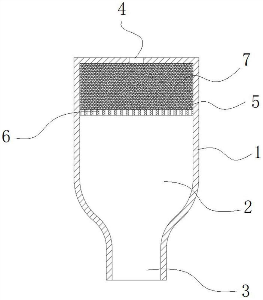
[0034] A complete vertical oil recovery filter structure for engine crankcases, including: an oil filter tank 1 installed vertically and connected to the inside of the crankcase, the middle section of the oil filter tank 1 is a gas buffer recovery chamber 2, and the bottom is connected to the crankshaft The liquid gas inlet and outlet 3 inside the box has a small air outlet 4 on the top, the upper section of the oil filter tank 1 is a filter chamber 5, the top of the filter chamber 5 is a small air outlet 4, and the bottom is provided with a valve installed on the inner wall of the oil filter tank 1 The perforated partition 6 and the oil filter element 7 are placed in the filter chamber 5 .

[0035] Preferably, the oil filter tank 1 can be square, ellipsoidal or cylindrical, and the gas buffer recovery chamber 2 has a structure with a narrow bottom and a wide top. The narrow structure is more conducive to the backflow of the engine oil; the oil filter element 7 is a high tempe...

Embodiment 2

[0038] A method for fully recovering and filtering vertical machine oil used in engine crankcases, comprising the following steps:

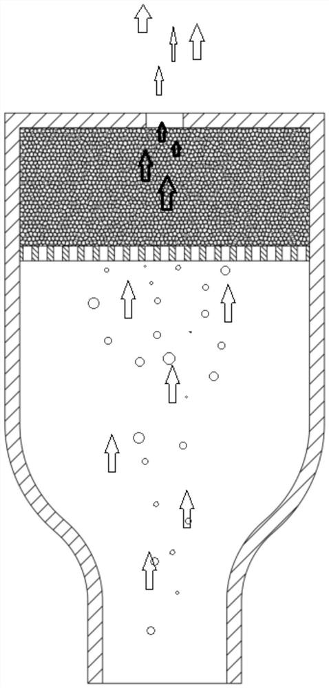
[0039] S1. The piston moves inward, and the gas in the crankcase and a large amount of mist oil are pressed into the oil filter tank 1 from the bottom step liquid gas inlet and outlet 3 of the oil filter tank 1;

[0040] S2. Gas and a large amount of mist oil pass through the oil filter element 7 in the filter chamber 5 on the upper part of the oil filter tank 1, the temperature of the gas decreases, and the oil-free gas is discharged from the small air outlet 4 on the top of the oil filter tank 1, and the condensed The mist oil is absorbed and intercepted by the filter element;

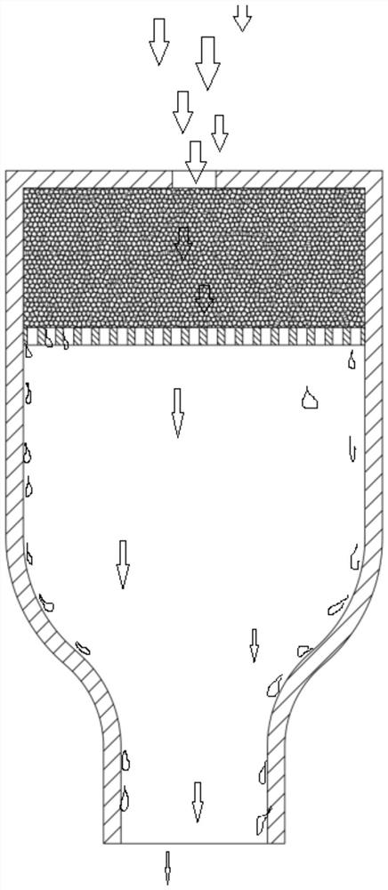
[0041] S3. The piston moves in reverse, forming a negative pressure in the crankcase and the oil filter tank 1, the external air is sucked in from the small air outlet 4, and the external air passes through the oil filter element 7 to cool the filter element, and at the...


PUM


Abstract

The invention discloses a vertical engine oil complete recycling and filtering structure and method for an engine crankcase. An engine oil filtering tank is vertically mounted in and communicated with the interior of the crankcase, the middle section of the engine oil filtering tank is provided with a gas buffering and recycling cavity, the bottom of the engine oil filtering tank is provided with a liquid-gas inlet and outlet connected to the interior of the crankcase, and a small air outlet is formed in the top of the engine oil filtering tank; and the upper section of the engine oil filtering tank is provided with a filtering chamber, the top of the filtering chamber is provided with a small air outlet, the bottom of the filtering chamber is provided with a perforated partition plate mounted on the inner wall of the engine oil filtering tank, and the engine oil filtering element is placed in the filtering chamber. According to the innovative structure, the integrated design of an engine is optimized on the whole, the recovery rate and recovery quality of engine oil are improved, and therefore the quality of the engine is improved on the whole, and the maintenance cost is reduced.

Description

technical field [0001] The invention relates to the technical field of engine equipment, mainly the technology of oil filtration and recovery, in particular to a complete vertical oil recovery and filtration structure and method for engine crankcases. Background technique [0002] The part of the cylinder block used to install the crankshaft is called the crankcase. In the prior art, the upper crankcase and the cylinder block are cast as one, and the lower crankcase is used to store lubricating oil and close the upper crankcase, so it is also called the oil pan diagram. The oil pan bears little force and is generally made of sheet steel stamping. Its shape depends on the overall layout of the engine and the capacity of oil. [0003] Crankshaft lubrication mainly refers to the lubrication of the bearing pad between the rocker arm and the lubrication of the fixed points at both ends. There will be an oil passage in the middle of the crankshaft that communicates with each bear...

Claims


Application Information

Patent Timeline
Patent Type & Authority Applications(China)
IPC IPC(8): F01M13/04F01M13/02
CPCF01M13/04F01M13/021F01M2013/0438F01M2013/0411
Inventor 万涛
Owner 云南优航无人机科技有限公司
Why Eureka
Try Eureka