Aperture-adjustable server cabinet surface punching and auxiliary stripping device
A technology for server cabinets and stripping devices, which is applied in the field of punching holes on the surface of server cabinets and auxiliary stripping devices, and can solve problems that affect the efficiency of punching holes on the surface of server cabinets, affect the use of punching equipment, and easily get stuck in punching parts. , to achieve the effect of good drilling operation, convenient aperture adjustment operation, and convenient removal operation
- Summary
- Abstract
- Description
- Claims
- Application Information
AI Technical Summary
Problems solved by technology
Method used
Image
Examples
Embodiment 1
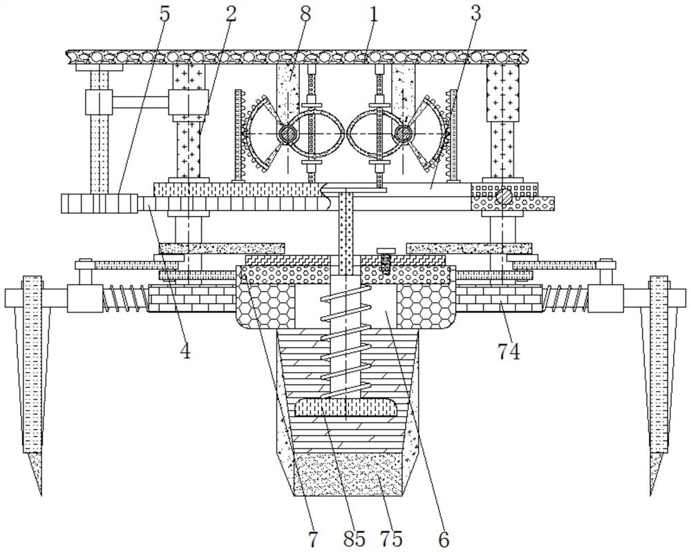
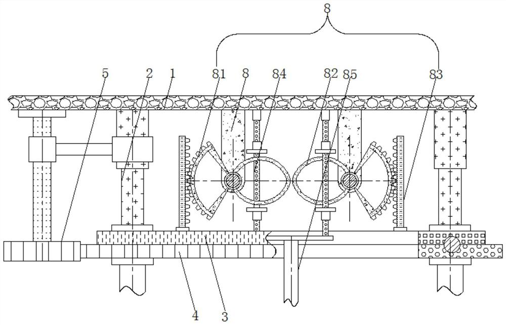
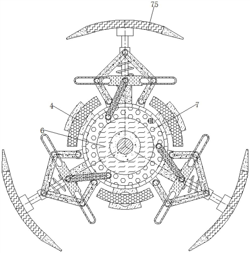
[0028] see Figure 1-4 , a surface punching and auxiliary stripping device for a server cabinet with adjustable aperture, including a body 1, the lower surface of the body 1 is provided with a driving rod 2, which is used to drive the support plate 3 to move, the driving rod 2 is designed with a hydraulic rod, and drives The lower end of the rod 2 is provided with a support plate 3, the support plate 3 is designed as an annular plate, and is used to drive the turntable 4 and the tooth plate 83 to move, the lower surface of the support plate 3 is connected to the turntable 4, and the outer surface of the turntable 4 is designed with a gear ring , matched with the drive gear 5, used to drive the base 6 to rotate.
[0029] The side surface of the turntable 4 is provided with a drive gear 5, which meshes with the ring gear on the outer surface of the turntable 4 to drive the turntable 4 to rotate. The lower surface of the turntable 4 is provided with a base 6, and the upper surfac...
Embodiment 2
[0033] see Figure 1-4 , a surface punching and auxiliary stripping device for a server cabinet with adjustable aperture, including a body 1, the lower surface of the body 1 is provided with a driving rod 2, which is used to drive the support plate 3 to move, the driving rod 2 is designed with a hydraulic rod, and drives The lower end of the rod 2 is provided with a support plate 3, the support plate 3 is designed as an annular plate, and is used to drive the turntable 4 and the tooth plate 83 to move, the lower surface of the support plate 3 is connected to the turntable 4, and the outer surface of the turntable 4 is designed with a gear ring , matched with the drive gear 5, used to drive the base 6 to rotate.
[0034] The side surface of the turntable 4 is provided with a drive gear 5, which meshes with the ring gear on the outer surface of the turntable 4 to drive the turntable 4 to rotate. The lower surface of the turntable 4 is provided with a base 6, and the upper surfac...
Embodiment 3
[0037] see Figure 1-4, a surface punching and auxiliary stripping device for a server cabinet with adjustable aperture, including a body 1, the lower surface of the body 1 is provided with a driving rod 2, which is used to drive the support plate 3 to move, the driving rod 2 is designed with a hydraulic rod, and drives The lower end of the rod 2 is provided with a support plate 3, the support plate 3 is designed as an annular plate, and is used to drive the turntable 4 and the tooth plate 83 to move, the lower surface of the support plate 3 is connected to the turntable 4, and the outer surface of the turntable 4 is designed with a gear ring , matched with the drive gear 5, used to drive the base 6 to rotate.
[0038] The side surface of the turntable 4 is provided with a drive gear 5, which meshes with the ring gear on the outer surface of the turntable 4 to drive the turntable 4 to rotate. The lower surface of the turntable 4 is provided with a base 6, and the upper surface...
PUM
 Abstract
Description
Claims
Application Information
 - R&D
- Intellectual Property
- Life Sciences
- Materials
- Tech Scout
- Unparalleled Data Quality
- Higher Quality Content
- 60% Fewer Hallucinations
Browse by: Latest US Patents, China's latest patents, Technical Efficacy Thesaurus, Application Domain, Technology Topic, Popular Technical Reports.
© 2025 PatSnap. All rights reserved.Legal|Privacy policy|Modern Slavery Act Transparency Statement|Sitemap|About US| Contact US: help@patsnap.com


