Micromotor mounting plate punching device based on crack detection and film positioning
A technology of crack detection and punching device, which is applied in metal processing and other directions, can solve the problems of slow processing of micro-motor mounting plates and inability to punch holes in multiple positions at the same time, so as to save processing time and improve processing speed.
- Summary
- Abstract
- Description
- Claims
- Application Information
AI Technical Summary
Problems solved by technology
Method used
Image

Examples
Embodiment 1
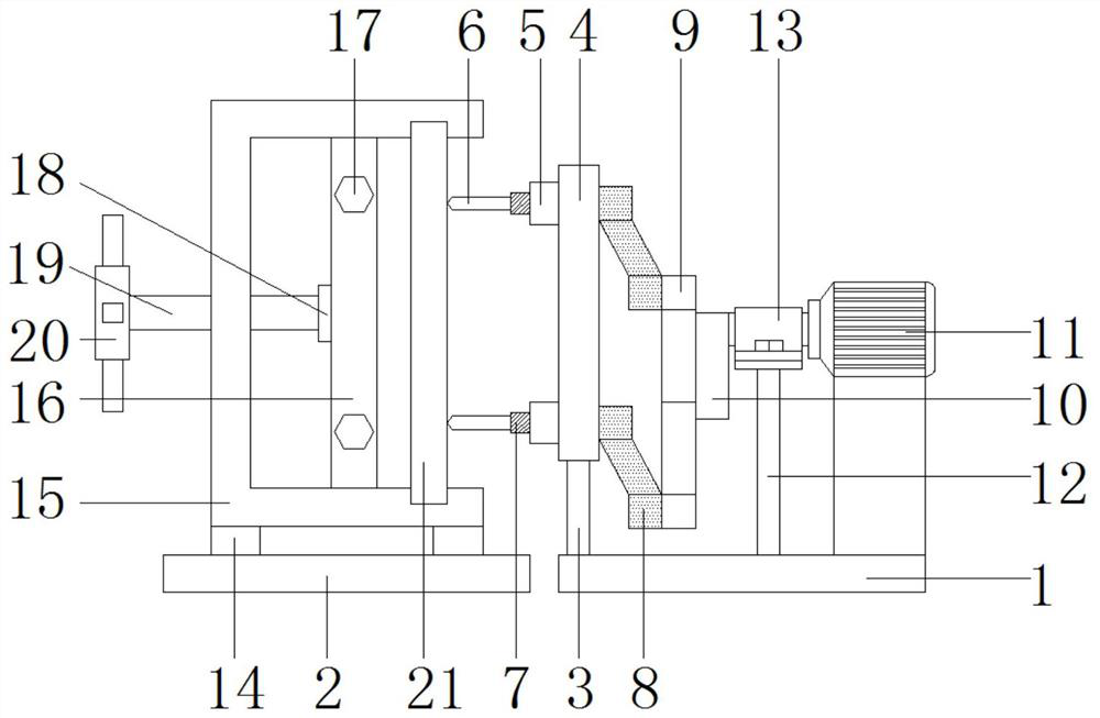
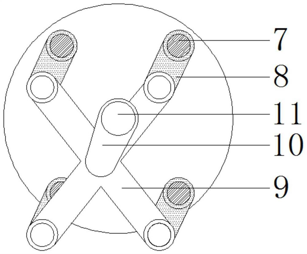
[0022] see Figure 1-2 , a micro-motor mounting plate punching device based on crack detection and film positioning, including a first base plate 1 and a second base plate 2, a support plate 3 is fixedly connected above the left end of the first base plate 1, and a circle is fixedly connected above the support plate 3 Disk 4, the left side of disk 4 is fixedly connected with the first bearing 5, the first bearing 5 is provided with four groups and evenly distributed on the outer wall of the disk 4; the inside of the first bearing 5 and the disk 4 is provided with a rotating sleeve 7 , the left end of the rotary sleeve 7 is fixedly equipped with a drill bit 6, and the right end is provided with a rotating oblique rod 8, the right side of the rotating oblique rod 8 is provided with a cross 9, the middle end of the cross 9 is provided with a rocking plate 10, and the right side of the rocking plate 10 is One end is fixedly connected with a high-speed motor 11 , and the lower part...
Embodiment 2
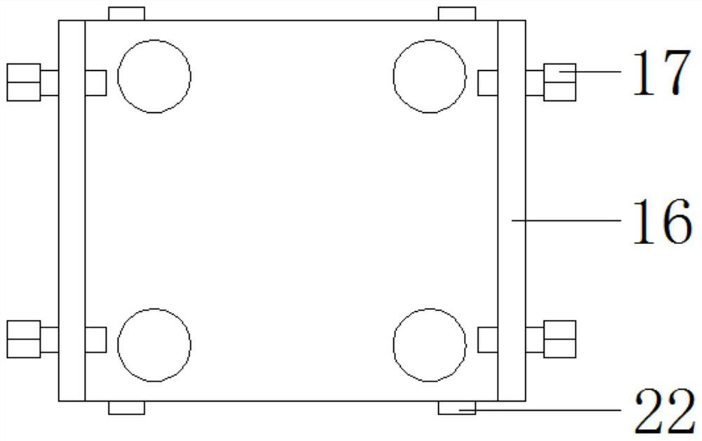
[0026] see figure 1 , 3 and Figure 4 , the upper two ends of the second bottom plate 2 are fixedly connected with pads 14, the top of the pads 14 is fixedly connected with a concave plate 15, the inside of the concave plate 15 is slidingly connected with a movable splint 16, and the left side of the movable splint 16 is fixedly connected There is a second bearing 18, the inside of the second bearing 18 is fixedly connected with a screw rod 19, and the screw rod 19 is screwed with the concave plate 15. A handle 20 is fixedly connected to the left end of the screw rod 19 . A mounting plate 21 is clamped inside the right side of the concave plate 15 . Adjusting bolts 17 are arranged on the front and rear sides of the movable splint 16 . A slide block 22 is fixedly connected to the top and bottom of the movable splint 16 , and the slide block 22 is slidably connected to the inside of the concave plate 15 .
[0027] Specifically, during use, the mounting plate 21 to be proces...
PUM
 Abstract
Description
Claims
Application Information
 - Generate Ideas
- Intellectual Property
- Life Sciences
- Materials
- Tech Scout
- Unparalleled Data Quality
- Higher Quality Content
- 60% Fewer Hallucinations
Browse by: Latest US Patents, China's latest patents, Technical Efficacy Thesaurus, Application Domain, Technology Topic, Popular Technical Reports.
© 2025 PatSnap. All rights reserved.Legal|Privacy policy|Modern Slavery Act Transparency Statement|Sitemap|About US| Contact US: help@patsnap.com