Outdoor water pipeline heat preservation equipment for power plant

A technology for water pipelines and power plants, applied in the field of outdoor water pipeline insulation equipment, can solve problems such as uneven coating of glue, stains on the surface of pipelines, and unsatisfactory bonding effect between thermal insulation tapes and pipelines, so as to improve work efficiency and improve work efficiency. High efficiency, good coating and laminating effect

Pending Publication Date: 2022-01-28
HUANENG JIAXIANG POWER GENERATION CO LTD
View PDF0 Cites 1 Cited by
  • Summary
  • Abstract
  • Description
  • Claims
  • Application Information

AI Technical Summary

Problems solved by technology

[0003] At present, thermal power plants are equipped with a network of various water pipes outdoors, including pipes for transporting heat, and pipes for transporting fuel oil or lubricating oil. These pipes generally need to be covered with insulation structures to prevent overheating. In order to reduce the heat loss caused by low heat loss or pipeline freezing cracks, the existing technology often adopts the method of wrapping insulation tape to insulate pipelines, but in the actual insulation process of pipelines, due to many stains on the surface of pipelines and uneven glue coating, As a result, the actual bonding effect between the insulation belt and the pipeline is not ideal, so the present invention proposes an outdoor water pipeline insulation equipment for power plants to solve the problems raised in the above-mentioned background technology

Method used


Image

  • Outdoor water pipeline heat preservation equipment for power plant
  • Outdoor water pipeline heat preservation equipment for power plant
  • Outdoor water pipeline heat preservation equipment for power plant

Examples


Embodiment Construction

[0027] The following will clearly and completely describe the technical solutions in the embodiments of the present invention with reference to the accompanying drawings in the embodiments of the present invention. Obviously, the described embodiments are only some, not all, embodiments of the present invention.

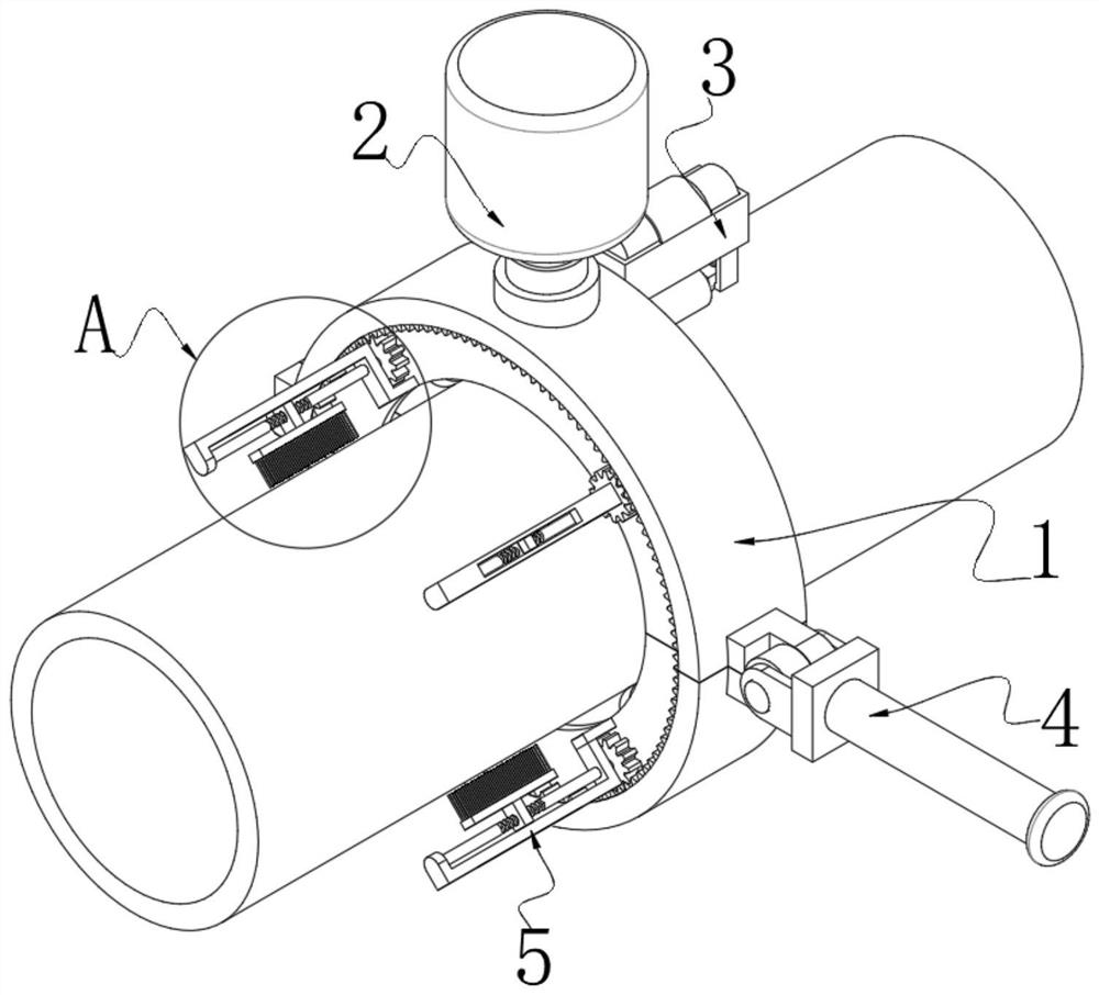
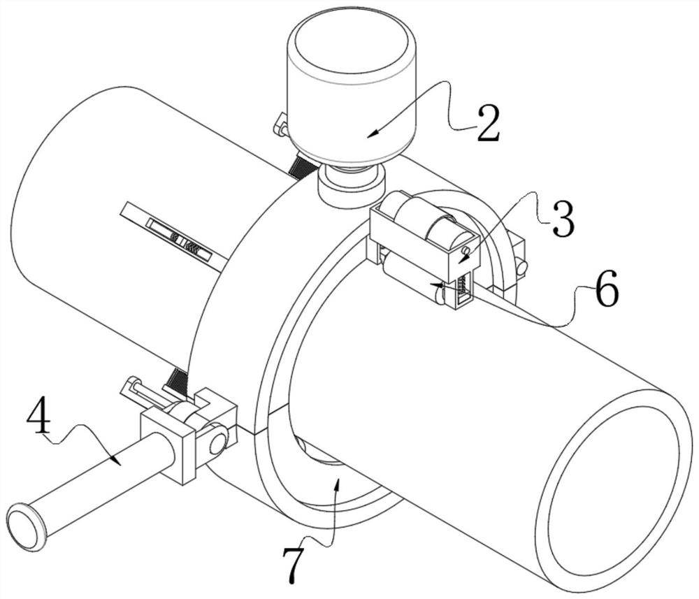
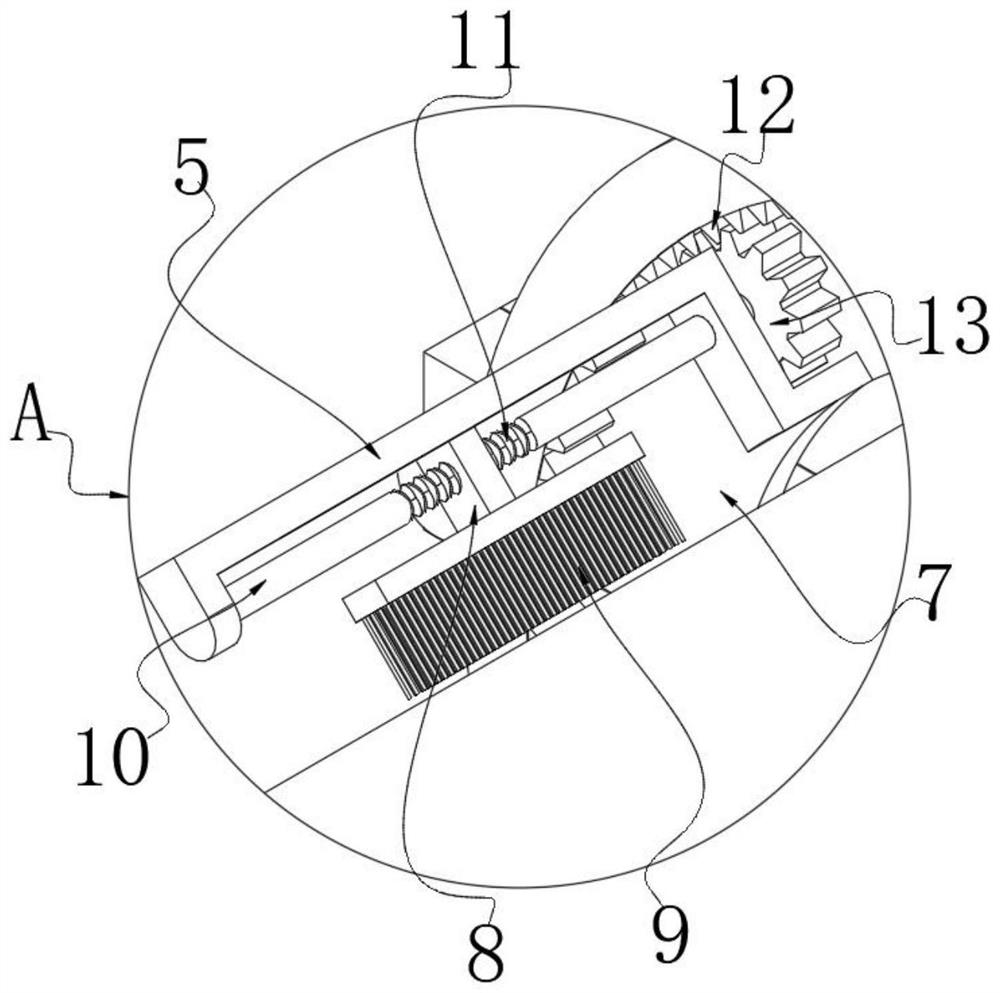
[0028] refer to Figure 1-7 , an outdoor water pipe heat preservation equipment used in power plants, including two device rings 1, one side of the device ring 1 is provided with a handle 4, and one end of the two device rings 1 is rotatably connected to the handle 4, the two devices The other end of the ring sleeve 1 is fixed with a connecting block, and a plug 16 is arranged between the two connecting blocks, and a socket corresponding to the plug 16 is opened inside the connecting block, so that the outdoor water pipe heat preservation equipment used in a power plant, When wrapping the heat preservation belt on the outdoor pipeline, first turn the two device ring ...


PUM


Abstract

The invention discloses outdoor water pipeline heat preservation equipment for a power plant, and relates to the technical field of pipeline heat preservation. The outdoor water pipeline heat preservation equipment comprises two device ring sleeves, a handle is arranged on sides of the device ring sleeves, ends of the two device ring sleeves are rotationally connected to the handle, and a plurality of cleaning frames are arranged on the front sides of the device ring sleeves; a glue solution tank is installed on the upper side of the device ring sleeve, a tape containing box is arranged on the rear side of the device ring sleeve, and a compression roller is arranged on the lower side of the tape containing box. The compression roller is pressed by the spring, so that the compression roller is tightly attached to the outer wall of the pipeline, and when a heat preservation belt wraps the pipeline along with translation rotation, the compression roller extrudes the heat preservation belt, so that the heat preservation belt is matched with a glue solution coated before, the heat preservation belt is comprehensively and uniformly attached to the outer wall of the pipeline, heat preservation treatment is conducted on the outdoor pipeline, and only the device needs to be translated; and in the moving process, the periphery of the pipeline is cleaned, coated with glue liquid and coated with the heat preservation belt, the coating and attaching effect is good, and the working efficiency is high.

Description

technical field [0001] The invention relates to the technical field of pipeline insulation, in particular to an outdoor water pipeline insulation equipment used in power plants. Background technique [0002] A power plant, also known as a power station, is a factory that converts various primary energy stored in nature into electrical energy (secondary energy). At the end of the 19th century, as the demand for electricity increased, people began to propose the idea of ​​establishing an electricity production center. With the development of motor manufacturing technology, the expansion of the application range of electric energy, and the rapid growth of the demand for electricity in production, power plants have emerged as the times require. Power plants have a variety of ways to generate electricity: those that rely on thermal power are called thermal power plants, those that rely on hydroelectric power are called hydropower plants, and some power plants that rely on solar ...

Claims


Application Information

Patent Timeline
IPC IPC(8): B29C65/52B05C1/06B05C11/10B08B9/023F16L59/02
CPCB29C65/52B29C66/80B29C66/0222B29C66/5326B05C1/06B05C11/10B08B9/023F16L59/028
Inventor 张宝华林涛仝彬楚良张卫东张伟
Owner HUANENG JIAXIANG POWER GENERATION CO LTD
Why Eureka
Try Eureka