
Electrochemistry-based material surface modification device

A surface modification and electrochemical technology, applied in the electrolysis process, electrolysis components, cells, etc., can solve the problem of time-consuming and labor-intensive, and achieve the effect of ensuring the constant concentration, ensuring the appearance and quality, and saving labor and time.

Pending Publication Date: 2022-01-28
XIANYANG NORMAL UNIV
View PDF0 Cites 0 Cited by
  • Summary
  • Abstract
  • Description
  • Claims
  • Application Information

AI Technical Summary

Problems solved by technology

[0004] In the electroplating process, in order to ensure the quality of the electroplating, the concentration of the electroplating solution should remain unchanged. However, during the electroplating process, the electroplating agent in the electroplating solution is continuously consumed. In the traditional electrochemical material surface modification device, the product Adding electroplating additives to the electroplating pool during the coating process is done manually, which requires weighing and proportioning, which consumes a lot of time and manpower. At the same time, it is necessary to ensure that the electroplating solution has a uniform concentration after adding the electroplating agent. Therefore, there is a need for an electrochemical-based material surface modification device

Method used


Image

  • Electrochemistry-based material surface modification device
  • Electrochemistry-based material surface modification device
  • Electrochemistry-based material surface modification device

Examples


Embodiment

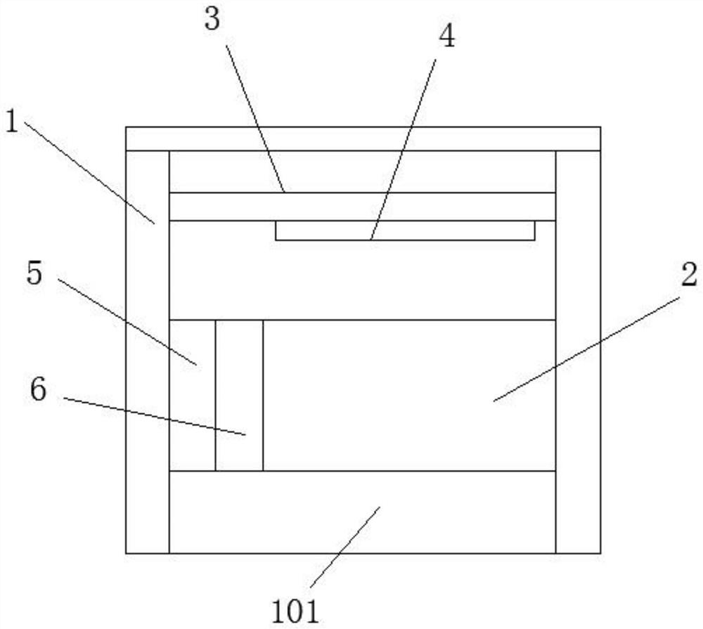
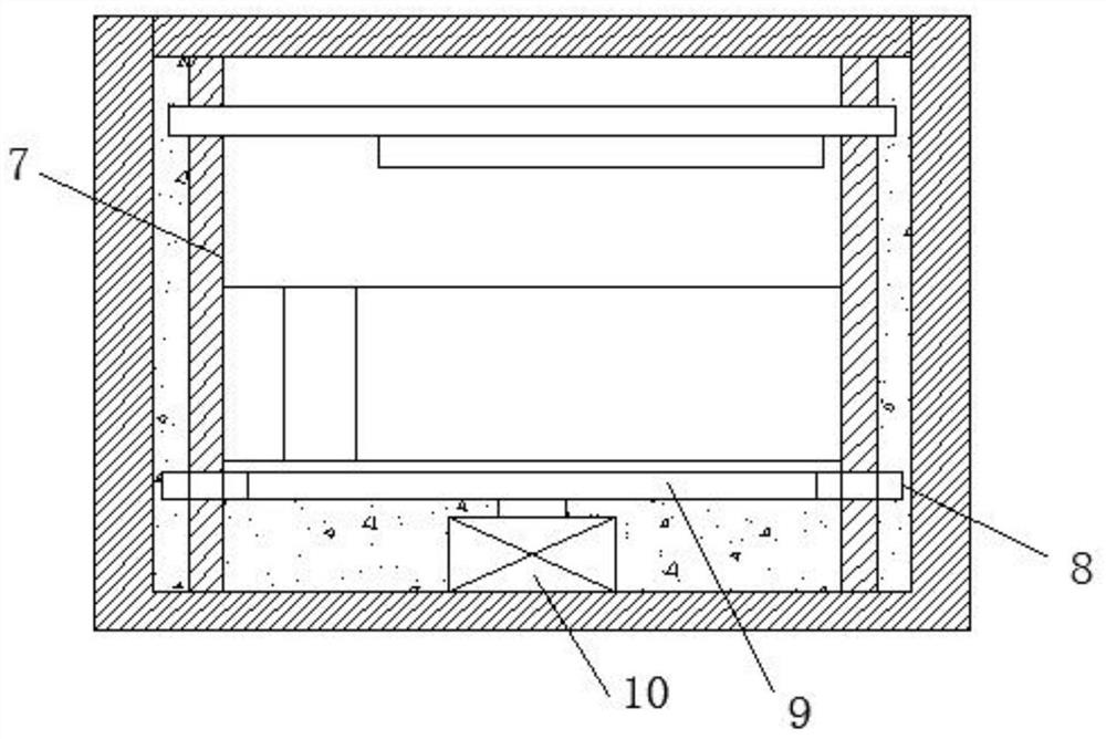
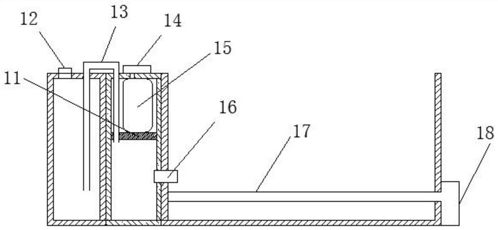
[0036] see Figure 1-Figure 3 , a material surface modification device based on electrochemistry, comprising a frame 1, an electroplating box 2 arranged on the frame 1, a low-voltage power supply electrically connected to the electroplating box 2, a fixed lifting device, a feeding device, and a feeding and stirring device

[0037] Specifically, in this embodiment, the fixed lifting device includes two lead screws 7, which are respectively arranged on both sides of the electroplating box 2. The threads on the two lead screws 7 are opposite, and a fixed lifting rod is arranged between the two lead screws 7. 3. The two ends of the fixed lifting rod 3 are threadedly connected with the lead screws 7 on both sides respectively, and the lower ends of the two lead screws 7 are provided with drive components;

[0038] Feeding device wherein comprises feeding box 6, is arranged on electroplating box 2 outer walls, is communicated with electroplating box 2 by one-way valve 16; , located...


PUM


Abstract

The invention relates to an electrochemistry-based material surface modification device which comprises a rack, an electroplating box arranged on the rack, a low-voltage power supply electrically connected with the electroplating box, a fixed lifting device and lead screws arranged on the two sides of the electroplating box respectively, a fixed lifting rod is arranged between the two lead screws, the two ends of the fixed lifting rod are in threaded connection with the lead screws on the two sides respectively, and driving assemblies are arranged at the lower ends of the two lead screws; a feeding device comprises a feeding box which is communicated with the electroplating box through a one-way valve; a pushing plate is arranged in the feeding box and is in sliding connection with the inner wall of the feeding box, the inflation air bag is located between the top of the feeding box and the pushing plate, an inflation pump is communicated with the inflation air bag, and the inflation pump is electrically connected with the low-voltage power supply; and a feeding and stirring device is used for uniformly stirring an electroplating additive fed into the electroplating box. According to the device, electroplating additives in the electroplating box and the feeding box can be automatically supplemented, a large amount of manpower and time are saved, it can be guaranteed that electroplating liquid in the electroplating box is uniform, and the appearance and quality of electroplating are effectively guaranteed.

Description

technical field [0001] The invention relates to the technical field of process equipment, in particular to an electrochemical-based material surface modification device. Background technique [0002] Surface modification refers to giving the surface new properties, such as hydrophilicity, biocompatibility, antistatic properties, dyeing properties, etc., on the premise of maintaining the original properties of materials or products. [0003] There are many reports on surface modification methods, which can generally be attributed to: surface chemical reaction method, surface grafting method, surface compounding method, etc.; surface modification technology is to use chemical and physical methods to change the surface of materials or workpieces. A class of heat treatment techniques that improve the properties of machine parts or materials by chemical composition or structure. The surface of the product can be coated by electrochemistry, and then the surface of the product can...

Claims


Application Information

Patent Timeline
IPC IPC(8): C25D17/00C25D21/10C25D21/12C25D21/14
CPCC25D17/00C25D21/10C25D21/12C25D21/14
Inventor 周贤明
Owner XIANYANG NORMAL UNIV
Learn More