Method for mutually converting CoaXPress interface data and Cameralink interface data
An interface data, mutual conversion technology, applied in data conversion, code conversion, electrical digital data processing and other directions, can solve the problems of low readout rate, slow readout, etc., to achieve the effect of small FPGA resource utilization
- Summary
- Abstract
- Description
- Claims
- Application Information
AI Technical Summary
Problems solved by technology
Method used
Image


Examples
Embodiment 1
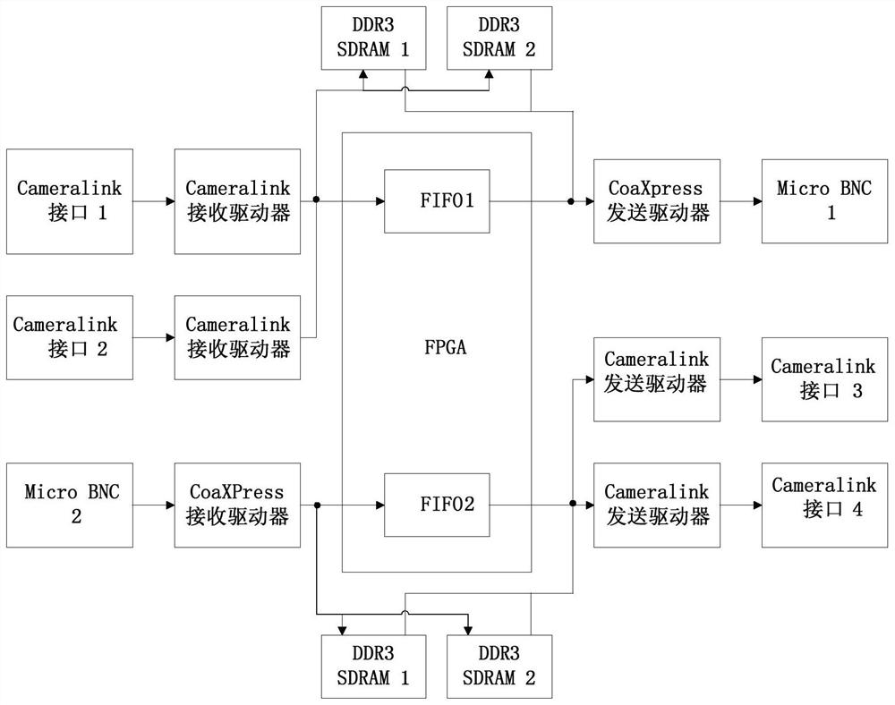
[0072] The purpose of this embodiment is to solve the problem of mutual conversion between CoaXPress and Cameralink interfaces, and to realize the interconnection and real-time transmission between two different interface devices. Xilinx Kintex-7 series FPGA is used as the main control logic element to carry out logic control on the reception and transmission between the two interfaces. The CoaXPress decoding chip is responsible for the conversion and reception of LVDS data to parallel data, and the CoaXPress encoding chip is responsible for the conversion and transmission of parallel data to LVDS serial data; the Cameralink decoding chip is responsible for the conversion and reception of LVDS data to parallel data, and the Cameralink encoding chip is responsible for parallel data Conversion and transmission to LVDS serial data. The invention can realize the conversion of the input data of the CoaXPress interface to the output data of the Cameralink interface, or the conversio...
Embodiment 2
[0078] The present embodiment provides a kind of Cameralink data interface and CoaXpress data interface mutual conversion method, and it comprises the following steps:
[0079] Step 1: The upper computer software configures the conversion mode through RS232;
[0080] Step 2: Convert Cameralink interface data to CoaXPress interface data;
[0081] Step 3: Convert CoaXPress interface data to Cameralink interface data.
[0082] Wherein said step 1 includes the following sub-steps:
[0083] The whole system is powered by DC 5V. After the system is powered on, the upper computer software communicates with the FPGA through the RS232 serial port, and the RS232 uses a DB9 connector. Configure the data input and output flow direction on the host computer interface, select CoaXPress as the input interface, and Cameralink as the output interface, then set the working mode as CoaXPress to Cameralink; select Cameralink as the input interface, and CoaXPress as the output interface, then s...
Embodiment 3
[0095] The present embodiment provides a kind of mutual conversion method of high-speed CoaXPress interface data and high-speed Cameralink interface data, and it comprises the following steps:
[0096] Step 1: The upper computer software configures the conversion mode through RS232;
[0097] Step 2: Convert Cameralink interface data to CoaXPress interface data;
[0098] Step 3: Convert CoaXPress interface data to Cameralink interface data.
[0099] Wherein, said step 1 includes the following sub-steps:
[0100] 1.1 After the system is powered on, start the host computer software and communicate with FPGA through RS232;
[0101] 1.2 Configure the input and output flow of data, and select the corresponding interface;
[0102] 1.3 For typical video formats, start this working mode directly;
[0103] 1.4 For uncommon video formats, set its pixel clock, resolution, and working timing, and then start the working mode;
[0104] Wherein, said step 2 includes the following sub-ste...
PUM
 Abstract
Description
Claims
Application Information
 - R&D
- Intellectual Property
- Life Sciences
- Materials
- Tech Scout
- Unparalleled Data Quality
- Higher Quality Content
- 60% Fewer Hallucinations
Browse by: Latest US Patents, China's latest patents, Technical Efficacy Thesaurus, Application Domain, Technology Topic, Popular Technical Reports.
© 2025 PatSnap. All rights reserved.Legal|Privacy policy|Modern Slavery Act Transparency Statement|Sitemap|About US| Contact US: help@patsnap.com