
Package antenna, package chip and on-chip antenna system

An on-chip antenna and chip-mounting technology, which is applied to antenna supports/mounting devices, antennas, antenna components, etc., can solve problems such as low antenna gain, secondary development of hardware, and restrictions on customer development at the application layer, achieving cost reduction, Effects of Simplified Packaging Process, Enhanced Flexibility and Compatibility

Pending Publication Date: 2022-01-28
北京晟德微集成电路科技有限公司
View PDF0 Cites 0 Cited by
  • Summary
  • Abstract
  • Description
  • Claims
  • Application Information

AI Technical Summary

Problems solved by technology

[0005] However, since the gain of the antenna on the chip is relatively low, it can only be used for short-distance scene detection requirements. In order to meet the long-distance detection requirements, it is often only necessary to change the antenna form without changing the chip structure.
However, the finalized packaged antenna application layer customers can no longer re-develop the hardware, which also limits the development of application layer customers.

Method used


Image

  • Package antenna, package chip and on-chip antenna system
  • Package antenna, package chip and on-chip antenna system
  • Package antenna, package chip and on-chip antenna system

Examples


Embodiment Construction

[0043] In order to facilitate the understanding of the present invention, the present invention will be described more fully below with reference to the associated drawings. Preferred embodiments of the invention are shown in the accompanying drawings. However, the present invention can be implemented in different forms and is not limited to the embodiments described herein. On the contrary, these embodiments are provided to make the understanding of the disclosure of the present invention more thorough and comprehensive.

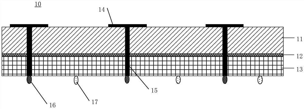
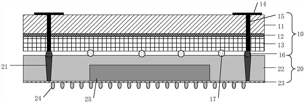
[0044] Such as figure 1 Shown is a schematic structural diagram of a packaged antenna provided by the present invention. The antenna-in-package 10 is formed by adopting BGA (Ball Grid Array, solder ball array package) packaging technology, for example, the antenna is designed on an independent PCB (Printed Circuit Board, printed circuit board) board, and the on-chip antenna system is implemented. Independent packaging of the antenna module. At the same ...


PUM


Abstract

The invention discloses a packaged antenna, a packaged chip and an on-chip antenna system. The packaged antenna comprises: a first dielectric substrate and a second dielectric substrate, which are oppositely arranged; at least one antenna unit, which is arranged on the surface, far away from the second dielectric substrate, of the first dielectric substrate at intervals; a grounding plate, which is arranged between the first dielectric substrate and the second dielectric substrate; at least one feed via hole, which penetrates through the first dielectric substrate, the grounding plate and the second dielectric substrate; and at least one first welding ball, which is arranged on the surface, far away from the first dielectric substrate, of the second dielectric substrate, wherein each antenna unit in the at least one antenna unit is electrically connected with one first welding ball through one feed via hole. According to the invention, the antenna module and the chip module can be independently packaged, so that the antenna module has the capability of re-packaging, the packaging process is simplified, the packaging cost is reduced, the application flexibility of the on-chip antenna is enhanced, and the on-chip antenna can be compatible with different application scenes.

Description

technical field [0001] The invention relates to the technical field of antennas, in particular to a packaged antenna, a packaged chip and an on-chip antenna system. Background technique [0002] With the development of millimeter wave technology, there are more and more millimeter wave antennas and radar applications. With the improvement of processing and preparation technology, the integration of products is higher and the volume is smaller. On-chip antennas are antennas designed on wafers, integrated circuits, and chips (such as radio frequency chips). They have the characteristics of high integration, compact structure, and fineness. [0003] The existing integration and packaging methods for chips and antennas are mainly divided into on-chip integration and on-chip integration, that is, the antenna is integrated into the package of the chip or the antenna is integrated on the top of the package of the chip. For on-chip integration, the antenna is mainly designed on th...

Claims


Application Information

Patent Timeline
Patent Type & Authority Applications(China)
IPC IPC(8): H01Q1/22H01Q1/50H01L23/29H01L23/488H01L23/528
CPCH01Q1/2283H01Q1/50H01L23/488H01L23/528H01L23/29
Inventor 杨华斌张健
Owner 北京晟德微集成电路科技有限公司
Learn More