Tube plate welding method, tube body and tube plate connecting method and heat exchanger
A technology of tube-sheet welding and tube-sheet connection, applied in heat exchanger shells, welding equipment, welding equipment, etc., can solve the problems of extremely high welding quality requirements, connection and sealing defects, etc., to reduce welding quality requirements and reduce rigidity Destruction chance and stability-enhancing effects
- Summary
- Abstract
- Description
- Claims
- Application Information
AI Technical Summary
Problems solved by technology
Method used
Image

Examples
Embodiment 1
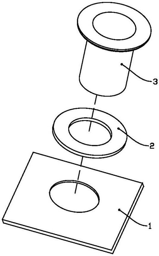
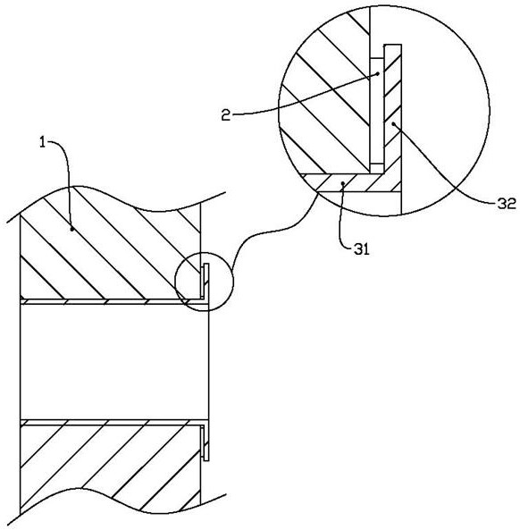
[0044] Such as figure 1 and 2 As shown, a tube sheet welding method is used for welding a tube sheet composed of a plate body 1, a sealing flat gasket 2 and an intermediate body 3; the plate body 1 includes a number of through holes; the intermediate body 3 includes a hollow cylinder section 31 And the convex edge 32, the outer wall of the hollow cylinder section 31 is attached to the inner wall of the through hole, and the convex edge 32 is drawn radially from one end of the hollow cylinder section 31; the flat sealing gasket 2 is flat, and is sandwiched between Between the plate body 1 and the convex edge 32;
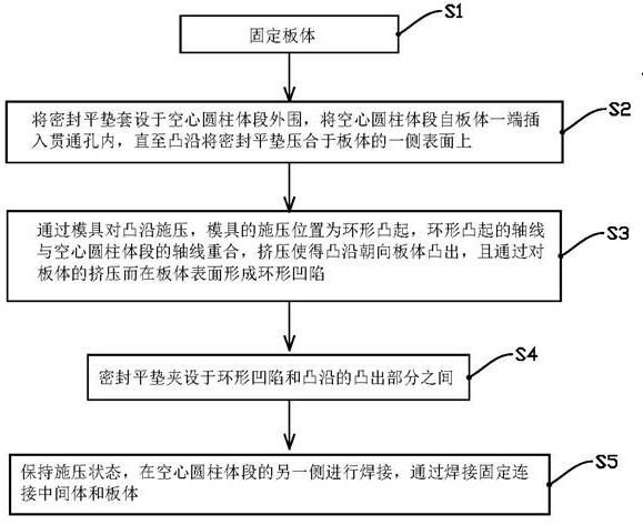
[0045] Such as image 3 As shown, the tube sheet welding method includes the following steps:
[0046] S1: fixed plate body 1;
[0047] S2: Put the sealing flat gasket 2 on the periphery of the hollow cylinder section 31, insert the hollow cylinder section 31 into the through hole from one end of the plate body 1 until the convex edge 32 presses the sealing flat g...
Embodiment 2
[0069] Such as Figure 9 As shown, the method for connecting the tube body 5 to the tube sheet includes the following steps:
[0070] A1: Put the sealing flat gasket 2 on the periphery of the hollow cylinder section 31, insert the hollow cylinder section 31 into the through hole from one end of the plate body 1, and press the sealing flat gasket 2 to one side of the plate body 1 until the convex edge 32 on the side surface;
[0071] A2: Fixed plate body 1;
[0072] A3: Apply pressure to the convex edge 32 through the mold 4. The pressing position of the mold 4 is the annular protrusion 41. The axis of the annular protrusion 41 coincides with the axis of the hollow cylinder section 31. Squeeze so that the convex edge 32 faces the plate body 1 protruding, and forming an annular depression on the surface of the plate body 1 by pressing the plate body 1;
[0073] A4: The sealing flat gasket 2 is sandwiched between the annular depression and the protruding part of the convex edg...
Embodiment 3
[0078] Such as Figure 10 As shown, the method for connecting the tube body 5 to the tube sheet includes the following steps:
[0079] B1: Put the sealing flat gasket 2 on the periphery of the hollow cylinder section 31, insert the hollow cylinder section 31 into the through hole from one end of the plate body 1, and press the sealing flat gasket 2 to one side of the plate body 1 until the convex edge 32 on the side surface;
[0080] B2: fixed plate body 1;
[0081] B3: Insert the pipe body 5 from the other side of the hollow cylinder section 31 relative to the set end of the convex edge 32, until the end of the pipe body 5 reaches the end of the hollow cylinder section 31, and ensure that the O-ring is in contact with the hollow cylinder section 31 The inner wall is bonded to achieve sealing;
[0082] B4: Apply pressure to the convex edge 32 through the mold 4. The pressing position of the mold 4 is the annular protrusion 41. The axis of the annular protrusion 41 coincides...
PUM
 Abstract
Description
Claims
Application Information
 - R&D
- Intellectual Property
- Life Sciences
- Materials
- Tech Scout
- Unparalleled Data Quality
- Higher Quality Content
- 60% Fewer Hallucinations
Browse by: Latest US Patents, China's latest patents, Technical Efficacy Thesaurus, Application Domain, Technology Topic, Popular Technical Reports.
© 2025 PatSnap. All rights reserved.Legal|Privacy policy|Modern Slavery Act Transparency Statement|Sitemap|About US| Contact US: help@patsnap.com