
Material tray conveying device and material counting system

A technology for conveying devices and trays, which is applied in the direction of conveyor control devices, conveyors, storage devices, etc., can solve the problems of labor cost, susceptibility to X-ray radiation, and physical health effects, so as to improve work efficiency and improve The efficiency of pointing materials and the effect of reducing potential safety hazards

Pending Publication Date: 2022-02-01
UNIVERSAL GLOBAL TECH KUNSHAN
View PDF8 Cites 0 Cited by
  • Summary
  • Abstract
  • Description
  • Claims
  • Application Information

AI Technical Summary

Problems solved by technology

[0003] However, at present, in the process of counting, there is no machine equipment specially used for loading and unloading trays. Usually, it is necessary to manually put the trays into the spotting machine for spotting, and then manually remove the trays from the spotting machine. Take it out and put it in the bin
In this case, the staff needs to cooperate with the dosing machine to complete the dosing action, and the dosing cannot leave halfway, which greatly consumes labor costs, and the efficiency of manual operation is low, and long-term loading and unloading of the material tray can easily cause the staff to feel fatigued. resulting in safety hazards
More importantly, if the staff stay close to the x-ray offline pointing machine for a long time, they are extremely vulnerable to x-ray radiation, which will also have a certain impact on their own health

Method used


Image

  • Material tray conveying device and material counting system
  • Material tray conveying device and material counting system
  • Material tray conveying device and material counting system

Examples


Embodiment Construction

[0075] In order to more clearly illustrate the technical solutions in the embodiments of the present invention or the prior art, the following will briefly introduce the drawings that need to be used in the description of the embodiments or the prior art. Obviously, the accompanying drawings in the following description are only These are some embodiments of the present invention. Those skilled in the art can also obtain other drawings based on these drawings without creative work.

[0076] In order to make the drawing concise, each drawing only schematically shows the parts related to the present invention, and they do not represent the actual structure of the product. In addition, to make the drawings concise and easy to understand, in some drawings, only one of the components having the same structure or function is schematically shown, or only one of them is marked. Herein, "a" not only means "only one", but also means "more than one".

[0077] It should also be further u...


PUM


Abstract

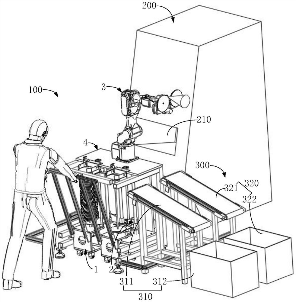
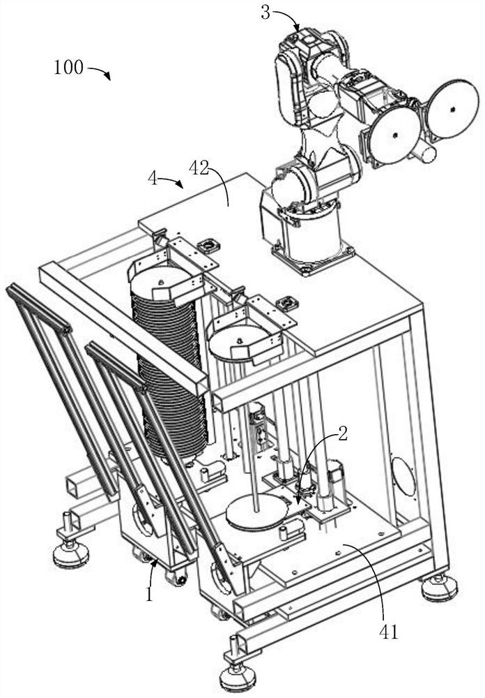
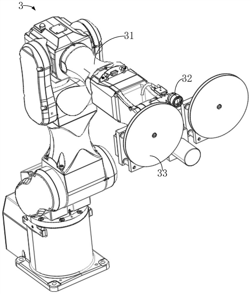
The invention discloses a material tray conveying device and a material counting system. The material tray conveying device comprises an operation platform, at least two jacking mechanisms, at least two trolley mechanisms and a material grabbing mechanism. The operation platform is provided with at least two feeding stations, and each feeding station is provided with a material taking part. A jacking mechanism is arranged at the position, corresponding to each material taking part, of the operation platform. The trolley mechanisms are used for bearing a plurality of trays. The trolley mechanisms are operably placed on the feeding stations. The jacking mechanisms are used for being matched with the trolley mechanisms in a butt joint mode and continuously conveying the trays located at the uppermost end into the material taking part at the same time interval. The material grabbing mechanism is used for reading data information of the trays located in the material taking part and grabbing the trays into a material counting machine. According to the device, automatic feeding and discharging of the trays can be rapidly achieved, the material counting machine can work rapidly and continuously, the trays subjected to material counting can be intelligently classified and collected, and therefore the labor cost can be greatly saved, and potential safety hazards of workers can be greatly reduced.

Description

technical field [0001] The invention relates to the field of material pointing technology, in particular to a material tray conveying device and a material pointing system. Background technique [0002] With the rapid development of science and technology, the assembly of a series of electronic products has been transformed from traditional manual implementation to production line automation. Every time the production line is completed, a lot of tailings need to be counted. At present, the most extensive and advanced method is to introduce an x-ray offline counting machine to count the tailings, which greatly improves the work efficiency and accuracy. [0003] However, at present, in the process of counting, there is no machine equipment specially used for loading and unloading trays. Usually, it is necessary to manually put the trays into the spotting machine for spotting, and then manually remove the trays from the spotting machine. Remove and place in basket. In this ca...

Claims


Application Information

Patent Timeline
IPC IPC(8): B65G47/91B65G43/08B65G1/04B65G35/00B07C5/36
CPCB65G47/918B65G43/08B65G1/04B65G35/00B07C5/362B65G2201/0258B65G2203/041
Inventor 王超亚张资易董锦军
Owner UNIVERSAL GLOBAL TECH KUNSHAN
Learn More