Argon recovery and purification device and purification method thereof

A technology of argon gas and vents, which is applied in the purification/separation of inert gases, chemical instruments and methods, inert gas compounds, etc., and can solve the problems of difficult intelligent switching of working groups and affecting purification efficiency, etc.

Pending Publication Date: 2022-02-01
安徽华中半导体材料有限公司
View PDF0 Cites 0 Cited by
  • Summary
  • Abstract
  • Description
  • Claims
  • Application Information

AI Technical Summary

Problems solved by technology

When the existing argon gas recovery and purification device is set up with a single working group, the purification efficiency will be affected. When multiple sets of working groups are set up, it is difficult to switch intelligently between the working groups

Method used


Image

  • Argon recovery and purification device and purification method thereof
  • Argon recovery and purification device and purification method thereof
  • Argon recovery and purification device and purification method thereof

Examples


Embodiment 1

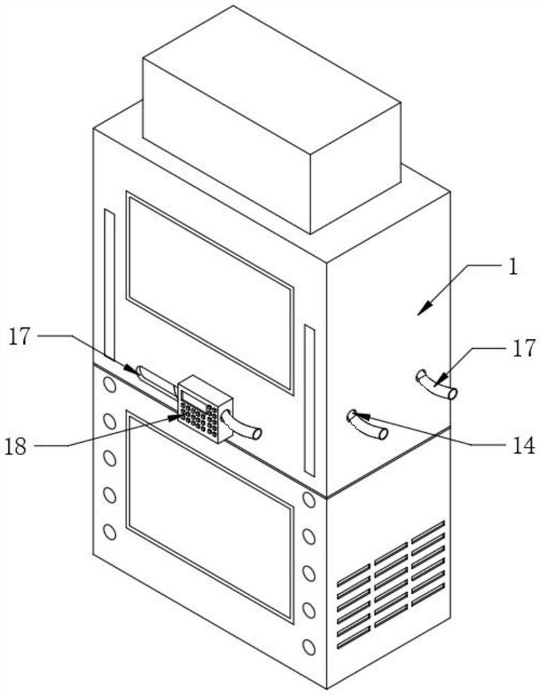
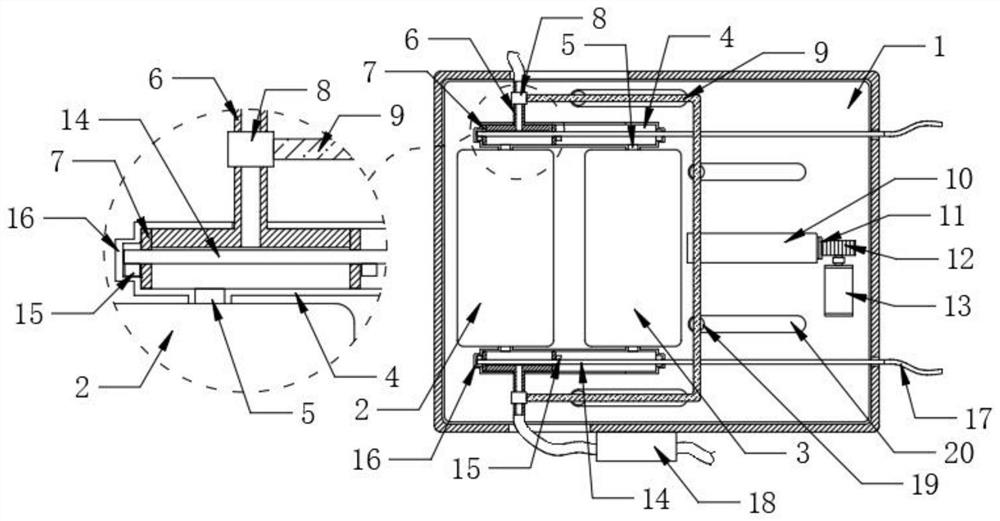
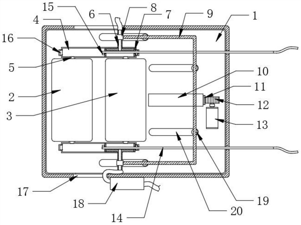
[0024] Such as Figure 1-3 As shown, the present invention proposes an argon gas recovery and purification device and its purification method, comprising a device main body 1, a first working group 2 and a second working group 3 are arranged in the device main body 1, and a pair of Argon gas shunt pipe 4, and two argon gas shunt pipes 4 are respectively located at the two ends of the first working group 2 and the second working group 3, and a single argon gas shunt pipe 4 is provided with a pair of vents 5, two vents 5 communicate with the first working group 2 and the second working group 3 respectively, and a shunt valve tube 6 can be slidably connected to the two argon gas shunt pipes 4, and the shunt valve pipe 6 includes a horizontal part and a vertical part, wherein the horizontal part It is located in the argon gas shunt pipe 4, and the two ends of the horizontal part are fixedly connected with the sealing sheet 7 at the corresponding position, and the vertical part is ...

Embodiment 2

[0027] Such as Figure 1-3 As shown, the present invention proposes an argon gas recovery and purification device and its purification method, comprising a device main body 1, a first working group 2 and a second working group 3 are arranged in the device main body 1, and a pair of Argon gas shunt pipe 4, and two argon gas shunt pipes 4 are respectively located at the two ends of the first working group 2 and the second working group 3, and a single argon gas shunt pipe 4 is provided with a pair of vents 5, two vents 5 communicate with the first working group 2 and the second working group 3 respectively, and a shunt valve tube 6 can be slidably connected to the two argon gas shunt pipes 4, and the shunt valve pipe 6 includes a horizontal part and a vertical part, wherein the horizontal part It is located in the argon gas shunt pipe 4, and the two ends of the horizontal part are fixedly connected with the sealing sheet 7 at the corresponding position, and the vertical part is ...


PUM


Abstract

The invention relates to the technical field of purification devices, in particular to an argon recovery and purification device and a purification method thereof. According to the technical scheme, the device comprises a device body, a first working set and a second working set are arranged in the device body, a pair of argon flow dividing pipes is fixedly connected in the device body, the two argon flow dividing pipes are located at the two ends of the first working set and the two ends of the second working set respectively, a pair of ventilation openings are formed in each argon flow dividing pipe, and the two ventilation openings are respectively communicated with the first working set and the second working set. Through the arrangement of the first working set and the second working set, uninterrupted argon recovery and purification work can be realized through switching between the first working set and the second working set; the first working set and the second working set can be intelligently and automatically switched, and the micro-oxygen analyzer not only can detect the purification degree of purified argon, but also can judge the working condition of the current working set according to the purity condition.

Description

technical field [0001] The invention relates to the technical field of purification devices, in particular to an argon recovery and purification device and a purification method thereof. Background technique [0002] Argon is a colorless, odorless monoatomic gas. The recovered and purified high-purity argon can be used for welding, stainless steel manufacturing, smelting, and chemical vapor deposition, crystal growth, thermal oxidation, Argon gas for epitaxy, diffusion, polysilicon, tungstenization, ion implantation, current carrying, sintering, etc. is used as a protective gas for the production of single crystal and polycrystalline silicon. When the existing argon gas recovery and purification device is set up with a single working group, the purification efficiency will be affected. When multiple sets of working groups are set up, it is difficult to switch intelligently between the working groups. Contents of the invention [0003] The object of the present invention i...

Claims


Application Information

Patent Timeline
IPC IPC(8): C01B23/00
CPCC01B23/001
Inventor 王帅张黎静吴骏
Owner 安徽华中半导体材料有限公司
Why Eureka
Try Eureka