Cantilever type pipe racking machine
A pipe rower and cantilever type technology, which is applied in the direction of drill pipe, casing, drilling equipment, etc., can solve the problems that the length is difficult to meet at the same time, the height of the support column is not large, and the length of the cantilever cannot be adjusted, so as to facilitate transportation and increase stability Sexuality, the effect of not easy to get stuck
- Summary
- Abstract
- Description
- Claims
- Application Information
AI Technical Summary
Problems solved by technology
Method used
Image
Examples
Embodiment 1
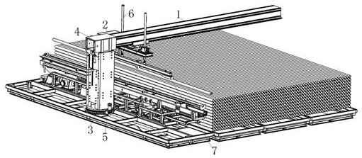
[0057] Combine below Figures 1 to 17 Specifically, the cantilever pipe row machine, such as figure 1 As shown, a cantilever pipe arrangement machine includes a cantilever 1, a trolley 2, a support column 3 and an electropermanent magnet 7. The trolley 2 is installed on the cantilever 1 and can move along the length direction of the cantilever 1. The electropermanent magnet 7 is installed on the trolley 2 below.
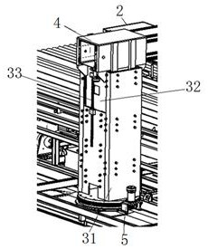
[0058] Such as figure 2 As shown, the support column 3 is an adjustable height support column, including an outer frame 31, a sliding body 32 and a linear telescopic device 34 (hydraulic cylinder); a slewing support device 5 is installed under the support column 3, and the slewing support device 5 includes external teeth. The support also includes a gear three and a hydraulic motor. The output end of the hydraulic motor is equipped with a gear three, and the gear three meshes with the external teeth of the external gear slewing bearing.
[0059] Such as Figure ...
Embodiment 2
[0082] The difference between this embodiment and Embodiment 1 is that the linear telescopic device 34 is an electric telescopic rod.
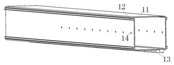
[0083] A slide block is installed on the inner surface of the cantilever mounting frame 4 corresponding to the guide rail 12 of the cantilever 1 , and the slide block can cooperate with the guide rail 12 .
[0084] The slewing bearing device 5 includes an external gear slewing bearing, a worm and a slewing motor (or hydraulic motor). A worm is installed at the output end of the rotary motor, and the worm meshes with the external teeth of the external tooth slewing bearing.
Embodiment 3
[0086] The difference between this embodiment and Embodiment 1 is: the cross-sections of the outer frame 31 of the support column 3 and the sliding body 32 are circular, and the outer periphery of the sliding body 32 is fixedly provided with a plurality of sliders 321, and the outer frame 31 is in contact with the sliding body. Block 321 is provided with a chute at the corresponding position.
[0087] The sleeve 61 and the telescopic rod 62 in the electro-permanent magnet adjustment device are threadedly connected, and the telescopic rod limiting device is no longer needed.
PUM
 Abstract
Description
Claims
Application Information
 - R&D
- Intellectual Property
- Life Sciences
- Materials
- Tech Scout
- Unparalleled Data Quality
- Higher Quality Content
- 60% Fewer Hallucinations
Browse by: Latest US Patents, China's latest patents, Technical Efficacy Thesaurus, Application Domain, Technology Topic, Popular Technical Reports.
© 2025 PatSnap. All rights reserved.Legal|Privacy policy|Modern Slavery Act Transparency Statement|Sitemap|About US| Contact US: help@patsnap.com


