
Automatically-controlled current-driven test device for electrically-controlled shock absorber

A technology of current drive and test device, applied in the direction of measuring device, instrument, measuring electricity, etc., can solve the problems of large current fluctuation, slow signal response and poor stability of electronically controlled shock absorber, achieve timely power supply, improve efficiency, use safe effect

Pending Publication Date: 2022-02-01
浙江万向马瑞利减震器有限公司 +1
View PDF0 Cites 0 Cited by
  • Summary
  • Abstract
  • Description
  • Claims
  • Application Information

AI Technical Summary

Problems solved by technology

[0003] 1. During the endurance test, the current input to the electronically controlled shock absorber has large fluctuations, poor stability, difficult control, and slow signal response;
[0004] 2. Manually adjusting the voltage and changing the current under different endurance cycle times requires employees to monitor the test process all the time, which is time-consuming and labor-intensive;

Method used


Image

  • Automatically-controlled current-driven test device for electrically-controlled shock absorber
  • Automatically-controlled current-driven test device for electrically-controlled shock absorber

Examples


Embodiment 1

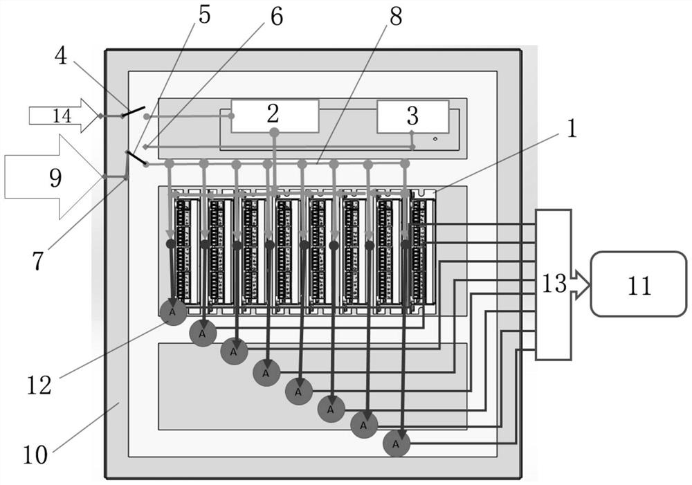
[0024] Embodiment 1: Voltage automatic control state, as attached figure 1 As shown, a kind of automatically controlled electronically controlled shock absorber current drive test device includes a box body 10, a power supply system and a current drive system are arranged in the box body 10, and the current drive system has eight current drivers 1, and the power supply system The system includes a power supply 2 and a voltage simulator 3, one end of the power supply 2 is electrically connected to the power switch 4 provided on the box 10, and the other end of the power supply 2 is electrically connected to each current driver 1 of the current drive system to realize power supply The power switch 4 is connected with the external AC circuit 14, and controls the power supply of the power supply 2; the gear switch 5 is located between the power supply system and the current drive system, and one end of the gear switch 5 is electrically connected with the voltage signal channel 8, a...

Embodiment 2

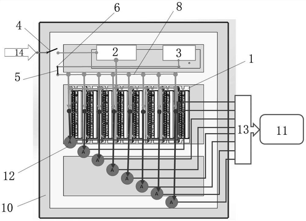
[0028] Example 2: Voltage manual control state, as attached figure 2 As shown, a kind of automatically controlled electronically controlled shock absorber current drive test device includes a box body 10, a power supply system and a current drive system are arranged in the box body 10, and the current drive system has eight current drivers 1, and the power supply system The system includes a power supply 2 and a voltage simulator 3, one end of the power supply 2 is electrically connected to the power switch 4 provided on the box 10, and the other end of the power supply 2 is electrically connected to each current driver 1 of the current drive system to realize power supply The power switch 4 is connected with the external AC circuit 14, and controls the power supply of the power supply 2; the gear switch 5 is located between the power supply system and the current drive system, and one end of the gear switch 5 is electrically connected with the voltage signal channel 8, and th...


PUM


Abstract

The invention discloses an automatically-controlled current-driven test device for an electrically-controlled shock absorber and belongs to the field of electrically-controlled shock absorbers. The automatically-controlled current-driven test device comprises a box body; a power supply system and a current driving system are arranged in the box body; the power supply system comprises a power supply and a voltage simulator; a power switch is connected with an external alternating-current circuit; a gear switch is arranged between the power supply system and the current driving system; one end of the gear switch is electrically connected with a voltage signal channel, and the other end of the gear switch is selectively and electrically connected with a manual gear port or an automatic gear port; the manual gear port is electrically connected with a voltage simulator, and the automatic gear port is electrically connected with an external testing machine; and each current driver converts an input voltage signal into a current signal and then transmits the current signal to the electrically-controlled shock absorber on a corresponding station through a wire. According to the automatically-controlled current-driven test device of the invention, current is stably, accurately and timely provided for a product in the durability verification process of the electrically-controlled shock absorber; and the whole valve train endurance test process of the electrically-controlled shock absorber on a multi-station valve train endurance platform is optimized.

Description

technical field [0001] The invention relates to the field of electronically controlled shock absorbers, in particular to an automatically controlled current-driven test device for electronically controlled shock absorbers. Background technique [0002] During the durability test of the valve system of the electronically controlled shock absorber, it is necessary to adjust the current input to meet the requirements of the change of the damping force value under different durability cycles. The existing conventional technology is to supply DC power (5-12V) to the electronically controlled shock absorber, and at the same time, after reaching a certain number of endurance cycles, manually adjust the power supply voltage and change the current to realize the change of the damping force value of the shock absorber . There is following defective in prior art: [0003] 1. During the endurance test, the current input to the electronically controlled shock absorber has large fluctua...

Claims


Application Information

Patent Timeline
IPC IPC(8): G01R31/00
CPCG01R31/00
Inventor 任洁雨王瀚琪杨磊赫建丽
Owner 浙江万向马瑞利减震器有限公司
Learn More