Sum and difference beam imaging target detection and precise angle measurement method

A target detection and difference beam technology, which is applied in radio wave measurement systems, measurement devices, radio wave reflection/reradiation, etc., can solve the problem that the detection accuracy cannot be affected by active phased array, coverage, shape, and linearity , time-consuming and other issues, to achieve a good application prospect, the effect of fast target angular coordinate measurement

Pending Publication Date: 2022-02-01
SUZHOU WEIMO ELECTRONIC INFORMATION TECH CO LTD
View PDF0 Cites 3 Cited by
  • Summary
  • Abstract
  • Description
  • Claims
  • Application Information

AI Technical Summary

Problems solved by technology

[0006] However, the above-mentioned active phased array radar detection technology still has many defects and deficiencies. On the one hand, the use of spatial multi-beam transmission technology needs to generate multiple detection pulses, which takes a long time and is greatly affected by target movement, especially for high-speed moving targets. , may lead to detection failure; on the other hand, the use of spatial multi-beam receiving technology, although the real-time performance is better, but the coverage, shape, and linearity of the synthesized poor beam will seriously affect the detection accuracy
At the same time, although most passive phased array radars use multi-mode and differential feeds to achieve single-pulse tracking, this technology cannot be used in active phased arrays, and passive phased arrays have been gradually replaced by active phased arrays. Eliminated

Method used


Image

  • Sum and difference beam imaging target detection and precise angle measurement method
  • Sum and difference beam imaging target detection and precise angle measurement method
  • Sum and difference beam imaging target detection and precise angle measurement method

Examples


Embodiment 1

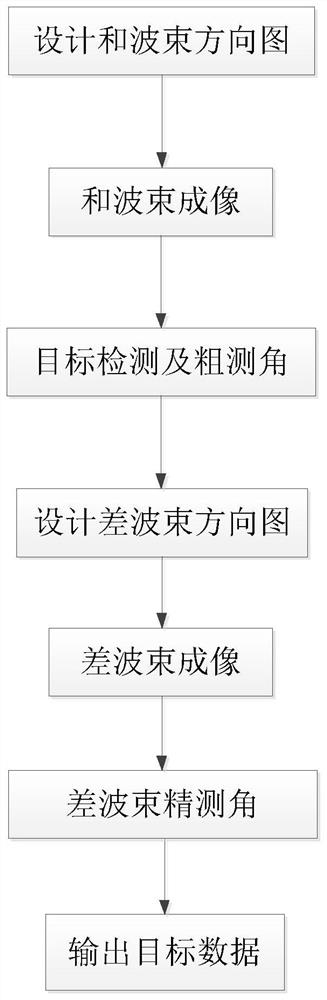
[0052] Embodiment 1: A kind of sum and difference beam imaging target detection and precise angle measurement method (see attached Figure 2-4 ),include:

[0053] Step 1: Design a sum beam pattern matching the detection target;

[0054] The designed sum beam pattern is a low-sidelobe high-gain acicular sum beam pattern, and the low-sidelobe high-gain acicular sum beam pattern is obtained by designing an array amplitude weighting method;

[0055] The array amplitude weighting method includes uniform distribution, cosine weighting, Hamming window, Taylor distribution, Chebyshev distribution and mixed weighting methods.

[0056] Step 2: performing beam imaging processing on the echo signals received by the array unit;

[0057] The echo signal received by the array unit is processed by summing beam imaging using the following method:

[0058]

[0059] Among them: j is the imaginary number unit, e is Euler's constant, For and beam image, is the target echo signal received...

Embodiment 2

[0081] Embodiment 2: A method for sum-difference beam imaging target detection and precise angle measurement, comprising:

[0082] Step 1: Design a sum beam pattern matching the detection target;

[0083] The designed sum beam pattern is a low-sidelobe high-gain acicular sum beam pattern, and the low-sidelobe high-gain acicular sum beam pattern is designed and obtained by a phase weighting method;

[0084] The phase weighting method includes genetic algorithm, particle swarm optimization algorithm, neural network and hybrid optimization method.

[0085] Step 2: performing beam imaging processing on the echo signals received by the array unit;

[0086] The echo signal received by the array unit is processed by summing beam imaging using the following method:

[0087]

[0088] Among them: j is the imaginary number unit, e is Euler's constant, For and beam image, is the target echo signal received by the array unit; A ∑ is the complex weight value of the array unit corr...


PUM


Abstract

The invention relates to the technical field of optical imaging, microwave imaging, radar detection, wireless communication, sonar, ultrasonic imaging and target detection and imaging recognition based on media such as sound, light and electricity, in particular to a sum and difference beam imaging target detection and precise angle measurement method and application thereof in the fields. The method comprises the following steps of: firstly, carrying out sum beam imaging processing on an echo signal received by an array unit, and carrying out target detection and amplitude comparison method angle measurement on an obtained sum beam imaging result; then, conducting difference beam imaging processing on the echo signal, on the basis, combining a sum beam target detection result and angle measurement data, and precisely measuring the angle coordinates of the target through difference beam nulling corresponding to the target, thus avoiding the influence of the difference beam coverage range, shape and linearity on the detection precision. Moreover, the precise angle coordinates of all targets can be obtained through one-time difference beam imaging, thereby achieving the precise and rapid measurement of the angular coordinates of the targets.

Description

technical field [0001] The invention relates to the technical fields of optical imaging, microwave imaging, radar detection, wireless communication, sonar, ultrasonic imaging, and target detection and imaging recognition based on media such as sound, light, and electricity, and specifically relates to a sum-difference beam imaging target detection and accurate measurement Angular methods and their applications in the various fields mentioned above. Background technique [0002] In the traditional radar detection technology, the target coordinates are usually measured by the ratio method, that is, the direction with the strongest target signal is used as its angular coordinate. tracking needs. [0003] In order to measure the angular coordinates of the target more accurately, the active phased array radar usually uses spatial difference beams to obtain accurate angular tracking parameters, that is, multiple beams with different spatial distributions are used to detect the ta...

Claims


Application Information

Patent Timeline
Patent Type & Authority Applications(China)
IPC IPC(8): G01S13/06G01S13/89
CPCG01S13/06G01S13/89
Inventor 张继龙张继康俞晓琳宋雨花张艺恒
Owner SUZHOU WEIMO ELECTRONIC INFORMATION TECH CO LTD
Why Eureka
Try Eureka