Novel double-electron-beam-channel folded waveguide slow-wave structure

A technology of electronic injection channel and folded waveguide, which is applied in the field of electromagnetic waves, can solve the problems of small coupling impedance and low loss characteristics, and achieve the effects of improving coupling impedance, large power capacity, increasing output power and electronic efficiency

Pending Publication Date: 2022-02-01
YANGTZE DELTA REGION INST OF UNIV OF ELECTRONICS SCI & TECH OF CHINE HUZHOU
View PDF6 Cites 2 Cited by
  • Summary
  • Abstract
  • Description
  • Claims
  • Application Information

AI Technical Summary

Problems solved by technology

[0004] The present invention provides a novel folded waveguide slow-wave structure with dual electron injection channels, which solves the problem of small coupling impedance of the existing folded waveguide slow-wave structure, and meanwhile, the structure has lower loss characteristics

Method used


Image

  • Novel double-electron-beam-channel folded waveguide slow-wave structure
  • Novel double-electron-beam-channel folded waveguide slow-wave structure
  • Novel double-electron-beam-channel folded waveguide slow-wave structure

Examples


Embodiment

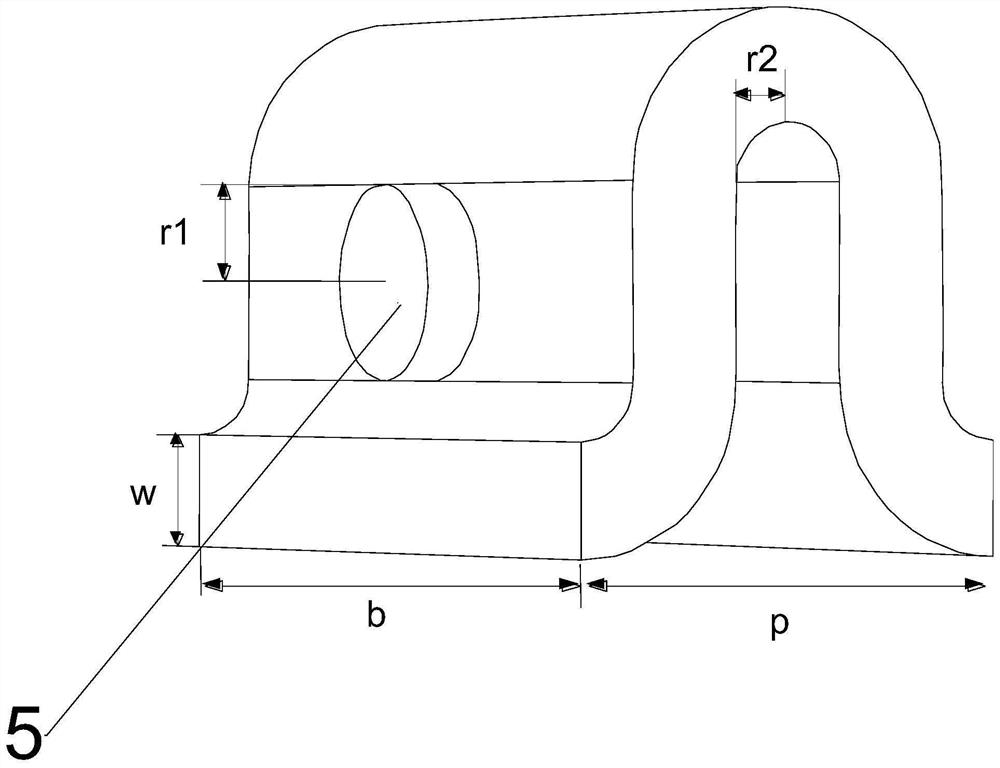
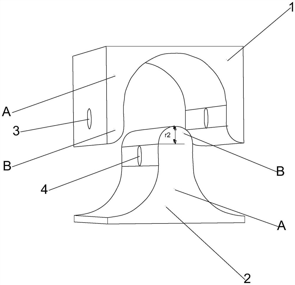
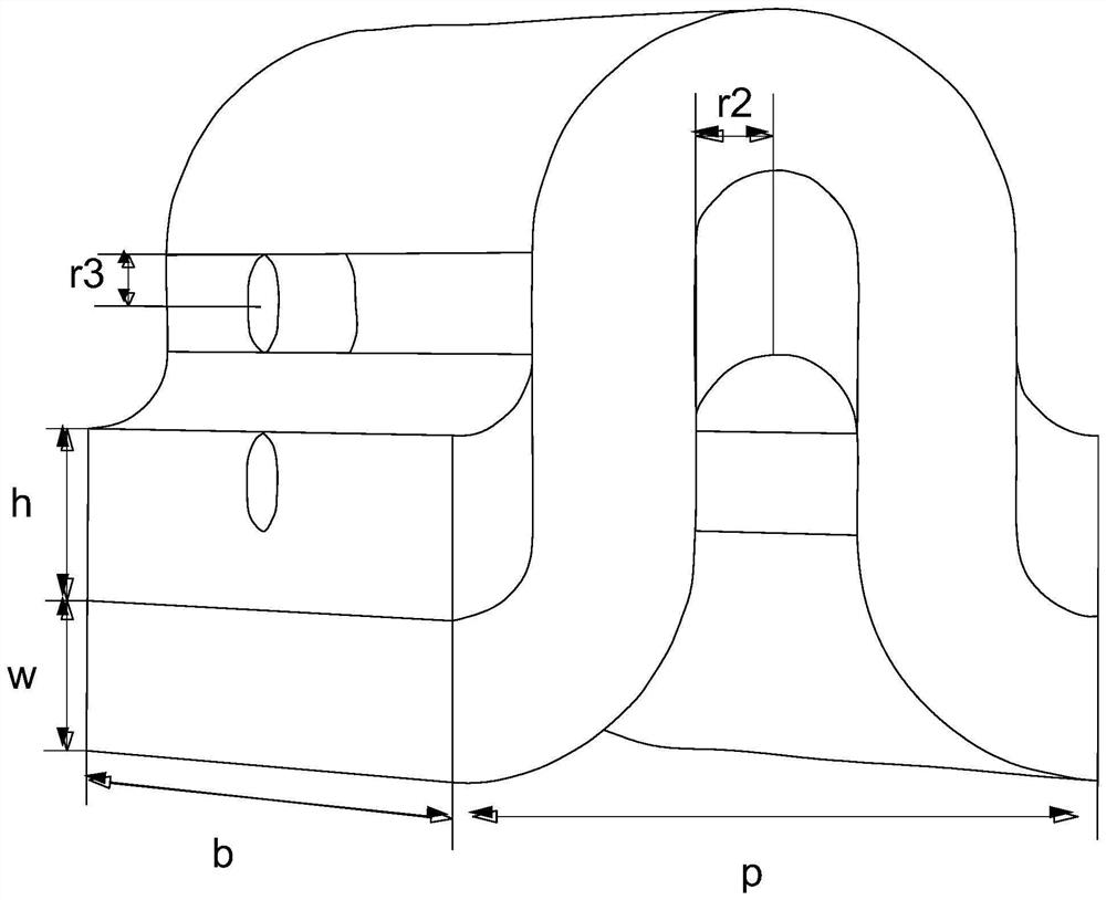
[0030] A novel dual-beam channel folded waveguide slow-wave structure, including folded waveguides, figure 1 is the vacuum model of a conventional folded waveguide, the blank space outside the vacuum model is the metal grid model, b is the length of the broad side of the waveguide, w is the length of the narrow side of the waveguide, p is the period length of the structure r1 is the radius of the electron injection channel, and r2 is Grid top circle radius. The structural dimensions are (unit: mm): b=1.95, w=0.26, p=1.04, r1=0.225, r2=0.13. Such as figure 1 As shown, the folded waveguide is provided with an upper row of grids 1 and a lower row of grids 2, and a distance is set between the upper row of grids 1 and the lower row of grids 2, and the upper row of grids 1 and the lower row of grids 2 are both Including the straight grid section A and the curved grid section B arranged tangentially to each other, the straight grid section A and the curved grid section B of the upp...


PUM


Abstract

The invention relates to the technical field of electromagnetic waves, and discloses a novel double-electron-beam-channel folded waveguide slow-wave structure. The structure comprises a folded waveguide, wherein an upper grid and a lower grid are arranged on the folded waveguide, a bent grid section of the upper grid is moved upwards or a bent grid section of the lower grid is moved downwards so as to allow the distance, perpendicular to a period direction, between the upper grid and the lower grid to be increased, a first cylindrical electron beam channel is arranged in the period direction and penetrates through the upper grid, the first electron beam channel is tangent to the top of the bent grid section of the lower grid, a second cylindrical electron beam channel is arranged in the period direction and penetrates through the lower grid, and the second electron beam channel is tangent to the bottom of the bent grid section of the upper grid. By increasing the distance between the upper grid and the lower grid, the radius of an original single electron beam channel is changed into a double electron beam channel which is established along the periodic direction and penetrates through the folded waveguide, so coupling impedance is effectively improved and loss is reduced under the condition that good dispersion characteristics are ensured.

Description

technical field [0001] The invention relates to the technical field of electromagnetic waves, in particular to a novel dual-electron injection channel folded waveguide slow-wave structure. Background technique [0002] Traveling wave tube is one of the most commonly used power amplifiers, and it is widely used in communication, radar, electronic countermeasures and other fields. [0003] The slow wave structure interaction circuit is the core part of the traveling wave tube, which is used to keep the phase speed synchronization of the electromagnetic wave and the electron beam, and produce continuous and effective energy exchange. The characteristics of the slow-wave structure largely determine the performance of the TWT. For a long time, improving and developing a new type of slow-wave system is one of the main directions to improve the performance of the TWT. Folded waveguide is a slow wave structure formed by bending a rectangular waveguide along the longitudinal directi...

Claims


Application Information

Patent Timeline
Patent Type & Authority Applications(China)
IPC IPC(8): H01J23/28
CPCH01J23/28
Inventor 段景瑞路志刚朱俊宛刘子璇钟宝辉王泽川陈海峰
Owner YANGTZE DELTA REGION INST OF UNIV OF ELECTRONICS SCI & TECH OF CHINE HUZHOU
Why Eureka
Try Eureka