Self-oxygenating device for fishery breeding
A self-replenishment and fishery technology, which is applied to drinking water devices, water supply devices, circuit devices, etc., can solve the problems of low efficiency and manpower consumption, and achieve the effects of convenient operation, high efficiency and stable operation
- Summary
- Abstract
- Description
- Claims
- Application Information
AI Technical Summary
Problems solved by technology
Method used
Image
Examples
Embodiment 1
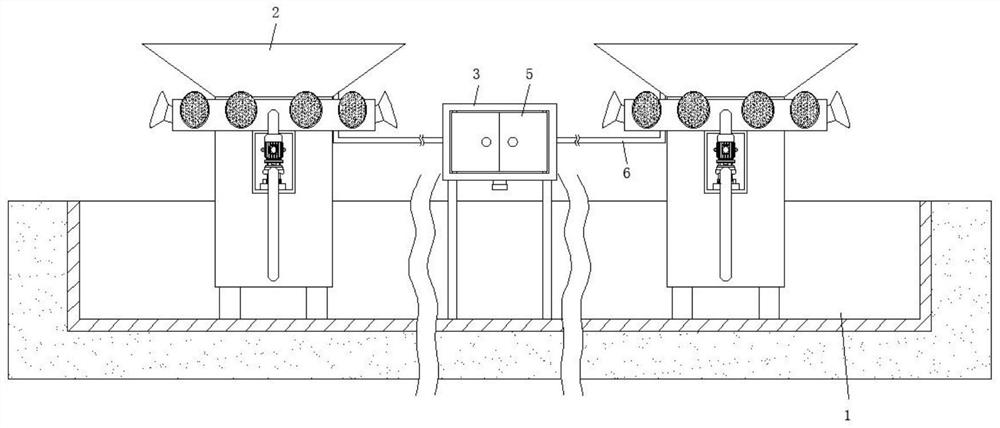
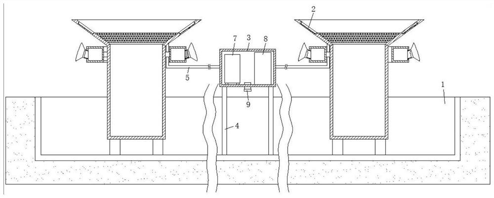
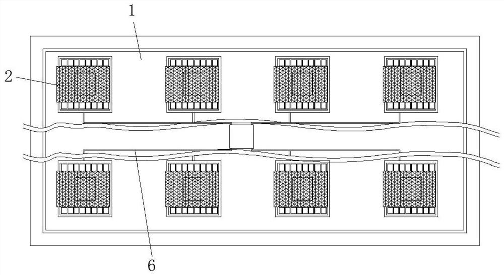
[0031] refer to Figure 1-6 , a self-oxygenation device for fish farming, comprising a culture pond body 1, a self-oxygenation mechanism 2 is installed in the culture pond body 1, and the self-oxygenation mechanism 2 includes a water collection tower 21, and the water collection tower 21 is fixed by the upper end of the water collection tower 21. The collection tray 22, the inner wall of the collection tray 22 is fixed with a drainage net 23. When the water is collected, the rainwater falls on the drainage net 23. At this time, the sundries are isolated by the drainage net 23, and the sundries can be smoothly collected from the collection tray under the impact of gravity and water. The rear side of the disc 22 slides out, thereby avoiding the occurrence of the clogging phenomenon of the water outlet of the water collection tower 21, and providing a certain guarantee for the long-term stable use of the device. Both are fixed with solar panels 24, and the upper side of the water...
Embodiment 2
[0033] like Figure 1-3 As shown, the present embodiment is basically the same as Embodiment 1. Preferably, the control system includes a control cabinet 3, and a cement column 4 is poured between the control cabinet 3 and the inner bottom surface of the culture pond body 1, and a folio is installed on the front side of the control cabinet 3. The sealed door body 5, the control cabinet 3 and the water collection tower 21 are connected with a threading pipe 6, the inner walls of the two sides of the control cabinet 3 are respectively installed with a controller 7 and a battery 8, and the middle part of the bottom surface of the control cabinet 3 is also installed with a sensor 9 , the sensing element 9 includes a temperature sensor, a humidity sensor and a camera.
[0034] In this embodiment, automatic control is realized by the automation system during use, and the sensor 9 monitors the state of the fish pond in real time. When it is found that there is no rain for a long time...
Embodiment 3
[0036] like Figure 1-3 As shown, this embodiment is basically the same as Embodiment 1. Preferably, the output ends of the temperature sensor, the humidity sensor and the camera are all electrically connected to the input end of the controller 7, and the power supply ends of the temperature sensor, the humidity sensor and the camera are all connected to the The output end of the storage battery 8 is electrically connected.
[0037] The output end of the solar panel 24 is electrically connected to the input end of the battery 8 , the power supply end of the micro water pump 29 is electrically connected to the output end of the battery 8 , and the control end of the micro water pump 29 is electrically connected to the output end of the controller 7 .
[0038] In this embodiment, all electrical components in the device are electrically connected by wires, and the connecting wires are placed in the threading tube, thereby achieving the effect of protecting the electrical devices ...
PUM
 Abstract
Description
Claims
Application Information
 - R&D
- Intellectual Property
- Life Sciences
- Materials
- Tech Scout
- Unparalleled Data Quality
- Higher Quality Content
- 60% Fewer Hallucinations
Browse by: Latest US Patents, China's latest patents, Technical Efficacy Thesaurus, Application Domain, Technology Topic, Popular Technical Reports.
© 2025 PatSnap. All rights reserved.Legal|Privacy policy|Modern Slavery Act Transparency Statement|Sitemap|About US| Contact US: help@patsnap.com


