Instrument foot stool for orthopaedic surgery

A technology of plastic surgery and instruments, applied in the field of medical equipment, can solve the problems of fixed instrument tripod structure, large space occupation, inconvenient contraction, etc., to achieve the effect of facilitating storage or moving, reducing space occupation, and convenient use

Inactive Publication Date: 2022-02-08
THE PEOPLES HOSPITAL SHAANXI PROV
View PDF0 Cites 0 Cited by
  • Summary
  • Abstract
  • Description
  • Claims
  • Application Information

AI Technical Summary

Problems solved by technology

[0004] The purpose of the present invention is to solve the shortcomings of the instrument tripod structure is fixed, not easy to shrink when not in use, and occupy a large space, and propose a kind of orthopedic surgery instrument tripod

Method used


Image

  • Instrument foot stool for orthopaedic surgery
  • Instrument foot stool for orthopaedic surgery
  • Instrument foot stool for orthopaedic surgery

Examples


Embodiment 1

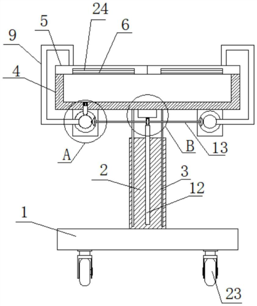
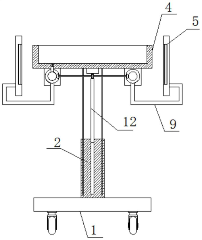
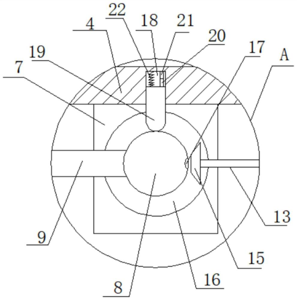
[0026] refer to Figure 1-5 , an instrument tripod for orthopedic surgery, comprising a base plate 1, a support plate 2 is fixedly installed on the top of the base plate 1, two lifting plates 3 are slidably installed on the top of the support plate 2, and two lifting plates 3 are fixedly installed on the top of the two lifting plates 3. A tray 4, the top of the tray 4 is provided with two top covers 5, and the bottom of the two top covers 5 is provided with a groove 24, and the ultraviolet lamp 6 is fixedly installed in the two grooves 24, and the bottom of the tray 4 is fixedly installed There are two fixed plates 7, the two fixed plates 7 are provided with a tray opening and closing mechanism, the bottom of the tray 4 is provided with an installation groove 18, and an ultraviolet lamp switch mechanism is arranged in the installation groove 18, and a motor 10 is fixedly installed on the bottom of the tray 4 One end of the worm screw 11 is fixedly installed on the output shaft...

Embodiment 2

[0042]The difference with Embodiment 1 is that: an instrument tripod for orthopedic surgery, including a base plate 1, a support plate 2 is fixedly installed on the top of the base plate 1, and two lifting plates 3 are slidably installed on the top of the support plate 2. The same tray 4 is fixedly installed on the top of the lifting plate 3, and the top of the tray 4 is provided with two top covers 5, and the bottoms of the two top covers 5 are provided with grooves 24, and ultraviolet rays are fixedly installed in the two grooves 24. The lamp 6 and the bottom of the tray 4 are fixedly equipped with two fixing plates 7, the two fixing plates 7 are provided with a tray opening and closing mechanism, the bottom of the tray 4 is provided with an installation groove 18, and an ultraviolet light switch mechanism is arranged in the installation groove 18, The bottom of tray 4 is fixedly installed with motor 10, and one end of worm 11 is fixedly installed on the output shaft of motor...


PUM


Abstract

The invention belongs to the technical field of medical instruments, and particularly relates to an instrument foot stool for orthopaedic surgery, aiming at solving the problems that an instrument foot stool is fixed in structure, inconvenient to contract when not used and large in occupied space, the following scheme is provided: the instrument foot stool comprises a bottom plate, a supporting plate is fixedly mounted at the top of the bottom plate, two lifting plates are slidably mounted at the top of the supporting plate, a same tray is fixedly mounted at the tops of the two lifting plates, two top covers are arranged at the top of the tray, grooves are formed in the bottoms of the two top covers, ultraviolet lamps are fixedly mounted in the two grooves, two fixing plates are fixedly mounted at the bottom of the tray, tray opening and closing mechanisms are arranged on the two fixing plates, a mounting groove is formed in the bottom of the tray, and an ultraviolet lamp switching mechanism is arranged in the mounting groove. The tray can be lowered, the occupied space can be reduced, storage or movement is facilitated, meanwhile, medical instruments stored in the tray can be sterilized, the structure is simple, and use is convenient.

Description

technical field [0001] The invention relates to the technical field of medical equipment, in particular to an instrument tripod for orthopedic surgery. Background technique [0002] Plastic surgery is a branch of surgery, also known as plastic surgery or plastic surgery. The scope of treatment is mainly skin, muscle and bone trauma, diseases, congenital or acquired defects and deformities of tissues or organs. A large number of tools will be used, and these tools need to be supported by the instrument stand. [0003] The existing instrument tripod has a fixed structure, is not easy to shrink when not in use, and takes up a lot of space. Therefore, we propose an instrument tripod for orthopedic surgery to solve the above problems. Contents of the invention [0004] The object of the present invention is to solve the disadvantages of fixed instrument scaffold structure, inconvenient contraction when not in use, and large space occupation, and propose an instrument scaffold ...

Claims


Application Information

Patent Timeline
IPC IPC(8): A61B50/13A61B50/20A61B50/33A61B90/70A61L2/10
CPCA61B50/13A61B50/20A61B50/33A61B90/70A61L2/10A61B2050/0051A61L2202/16A61L2202/17A61L2202/182A61L2202/24
Inventor 韩锋慕生枝王国栋郑博文
Owner THE PEOPLES HOSPITAL SHAANXI PROV
Why Eureka
Try Eureka