
Solenoid valve coil assembly pin welding method and equipment

A technology of solenoid valve coil and welding equipment, applied in welding equipment, auxiliary welding equipment, welding/cutting auxiliary equipment, etc., can solve the problems of reduced production efficiency, difficult positioning of fixtures, irregular shapes of coil components and pins, etc. Achieve the effect of improving production efficiency and improving welding efficiency

Pending Publication Date: 2022-02-08
李士峰
View PDF0 Cites 2 Cited by
  • Summary
  • Abstract
  • Description
  • Claims
  • Application Information

AI Technical Summary

Problems solved by technology

[0004] 1. The two processes of welding and stamping require two sets of equipment to be carried out separately. After the workpiece completes a process, it must be unloaded first, then reloaded, and re-positioned, resulting in repeated positioning of the workpiece and reducing production efficiency.
[0005] 2. The shape of the bottom of the workpiece is complex, and it is difficult to locate it with conventional fixtures, and the middle part of the workpiece is wound with wires, which cannot be fixed by manipulator clamping, making it difficult to effectively locate the workpiece
[0007] 4. The frame body and the lower cover are not fixedly connected before stamping, and the middle part of the frame body is wound with wires. When turning over, it is necessary to pay attention not to clamp the wires. This makes the conventional turning device unable to be directly applied to the workpiece, and because the coil Components and pins are irregular in shape, you need to consider how to store them after flipping

Method used


Image

  • Solenoid valve coil assembly pin welding method and equipment
  • Solenoid valve coil assembly pin welding method and equipment
  • Solenoid valve coil assembly pin welding method and equipment

Examples


Embodiment Construction

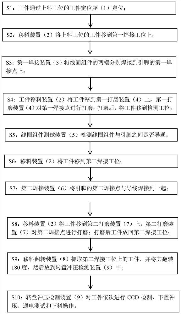
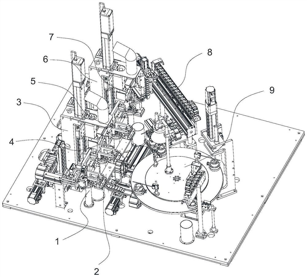
[0054] Such as figure 2 and Figure 4As shown, a solenoid valve coil assembly pin welding equipment, the equipment includes a frame and a workpiece positioning seat 1 installed on the frame, a material transfer device 2, a first welding device 3, a first grinding device 4, and a coil assembly A testing device 5, a second welding device 6, a second grinding device 7, a material shifting and turning device 8 and a turntable stamping detection device 9. Four workpiece positioning seats 1 are arranged side by side on the frame, and the above four workpiece positioning seats 1 form four stations, which are successively a feeding station, a first welding station, a testing station and a second welding station. The material shifting device 2 is arranged on the right side of the workpiece positioning seat 1, and the first welding device 3, the coil assembly testing device 5 and the second welding device 6 are arranged sequentially on the left side along the processing direction. Th...


PUM


Abstract

The invention relates to the technical field of solenoid valve production, in particular to a solenoid valve coil assembly pin welding method and equipment. The equipment comprises a workpiece positioning seat, a material moving device, a first welding device, a coil assembly testing device, a second welding device, a material moving and overturning device and a turntable stamping detection device; the material moving device is arranged on one side of the workpiece positioning seat, and the first welding device, the coil assembly testing device and the second welding device are sequentially arranged on the other side of the workpiece positioning seat in the machining direction; and a second welding station is connected with one end of a material moving and overturning device, and the other end of the material moving and overturning device is connected with the feeding end of the turntable stamping detection device. Welding operation is divided into the first welding station and the second welding station, the welding efficiency is improved, welded workpieces directly enter the rotary disc stamping detection device to be stamped, and the production efficiency is improved.

Description

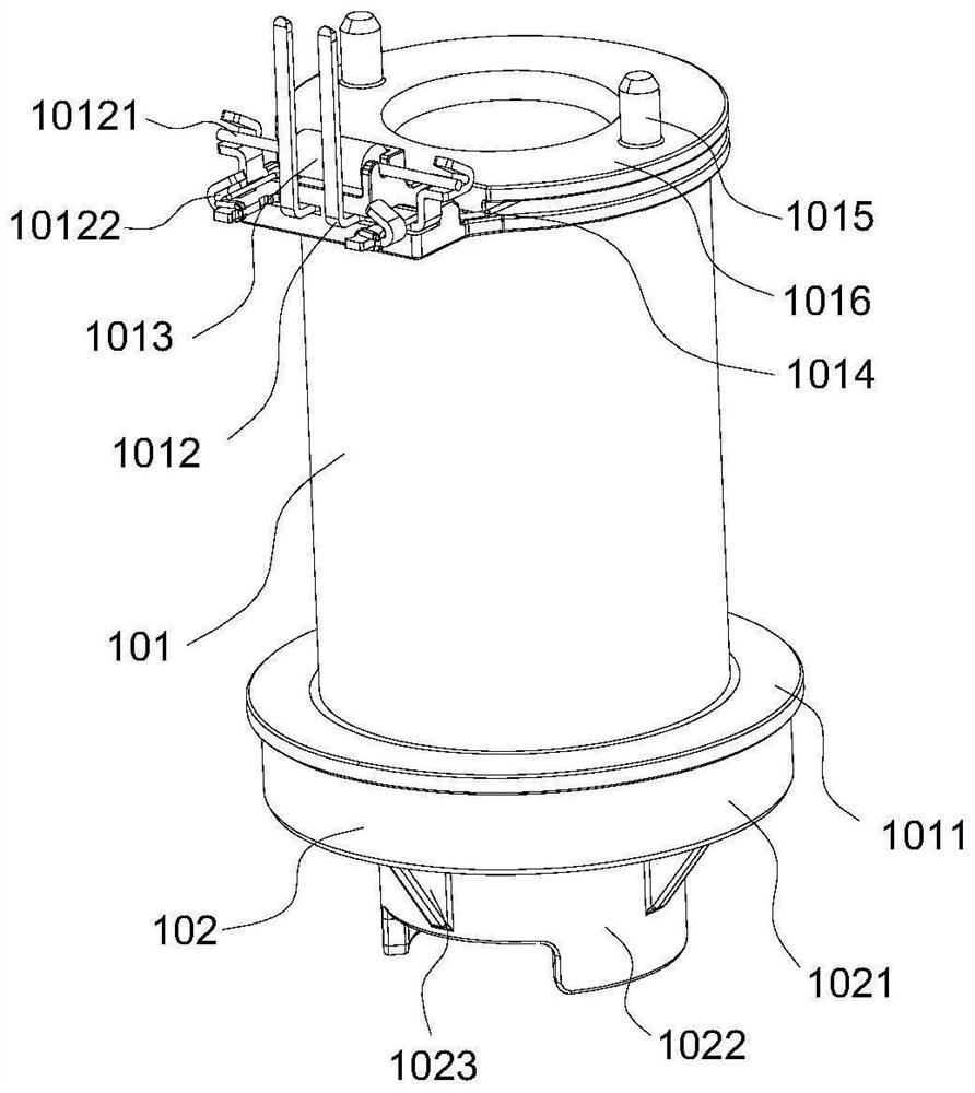
technical field [0001] The invention relates to the technical field of solenoid valve production, in particular to a method and equipment for welding the pins of a solenoid valve coil assembly. Background technique [0002] The solenoid valve coil assembly includes a skeleton body and a lower cover. The middle part of the skeleton body is columnar and is wound with wires, and the upper end and the lower end of the skeleton body are respectively provided with an upper limit ring and a lower limit ring. The lower part of the wire is limited by the lower limit ring. The upper part of the wire passes through the upper limit ring, and the upper limit ring is provided with a pair of symmetrical pins and a coil assembly. The pin is provided with a first welding point and a second welding point, and the end of the coil component is wound on the end of the pin and welded on the second welding point. The left and right ends of the coil assembly are welded on the first welding point...

Claims


Application Information

Patent Timeline
IPC IPC(8): B23P23/00B23K37/00B23K37/04
CPCB23P23/00B23K37/00B23K37/0443
Inventor 李士峰
Owner 李士峰
Learn More