Excavation trolley automatic lifting hydraulic device

An automatic lifting and hydraulic device technology, which is applied in the direction of lifting devices, fluid pressure actuating devices, lifting equipment safety devices, etc., can solve the problems of mechanical thermal deformation, damage and jamming of lifting hydraulic devices, and improve heat transfer and cooling effect, good heat dissipation and cooling effect, and the effect of preventing excessive temperature

Pending Publication Date: 2022-02-08
GUIZHOU UNIV
View PDF7 Cites 0 Cited by
  • Summary
  • Abstract
  • Description
  • Claims
  • Application Information

AI Technical Summary

Problems solved by technology

[0007] The purpose of the present invention is to provide an automatic lifting hydraulic device for excavating trolleys to solve the problem that the existing lifting hydraulic devices on the market proposed by the above-mentioned background technology are inconvenient to play a good role in heat dissipation and cooling during use, so that The temperature rise of the lifting hydraulic device will cause the oil to heat up, which in turn will increase the temperature of the hydraulic cylinder. The temperature rise of the hydraulic cylinder will easily cause thermal deformation of the machine, and the moving parts with different thermal expansion coefficients in the hydraulic components will become smaller due to their fit clearance. And stuck, causing action failure, affecting the transmission accuracy of the hydraulic system, lack of certain anti-collision protection measures, so when the cylinder of the lifting hydraulic device directly collides with a hard object during the use of the excavation trolley, it is easy to Problems causing damage to lifting hydraulic devices

Method used


Image

  • Excavation trolley automatic lifting hydraulic device
  • Excavation trolley automatic lifting hydraulic device
  • Excavation trolley automatic lifting hydraulic device

Examples


Embodiment Construction

[0031] The following will clearly and completely describe the technical solutions in the embodiments of the present invention with reference to the accompanying drawings in the embodiments of the present invention. Obviously, the described embodiments are only some, not all, embodiments of the present invention. Based on the embodiments of the present invention, all other embodiments obtained by persons of ordinary skill in the art without making creative efforts belong to the protection scope of the present invention.

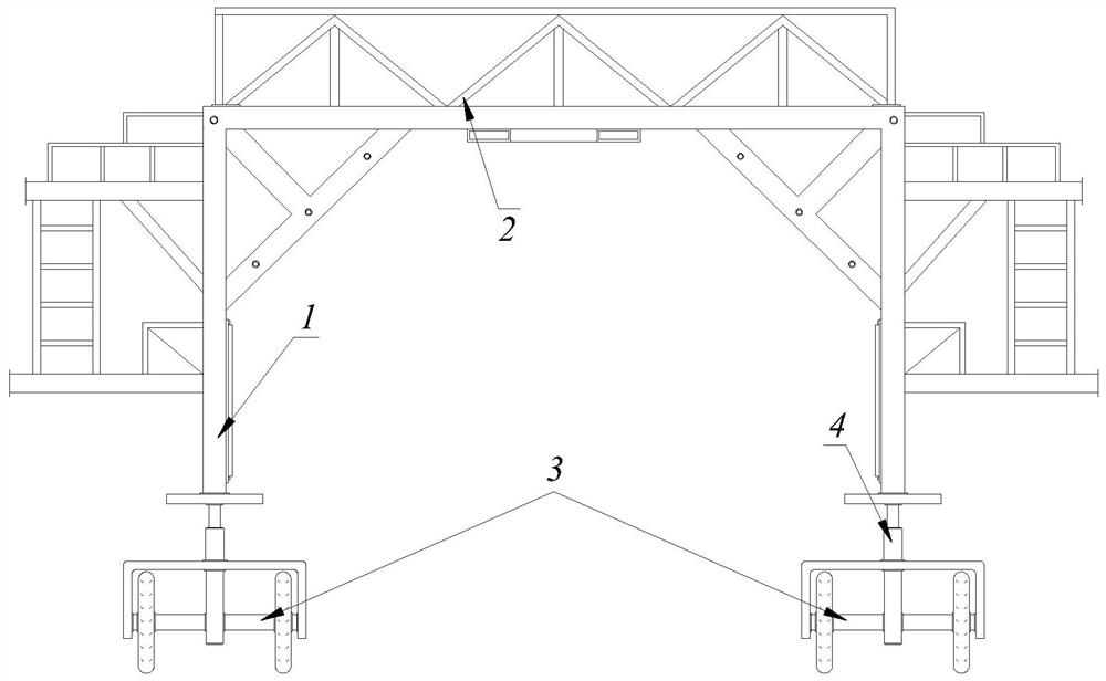
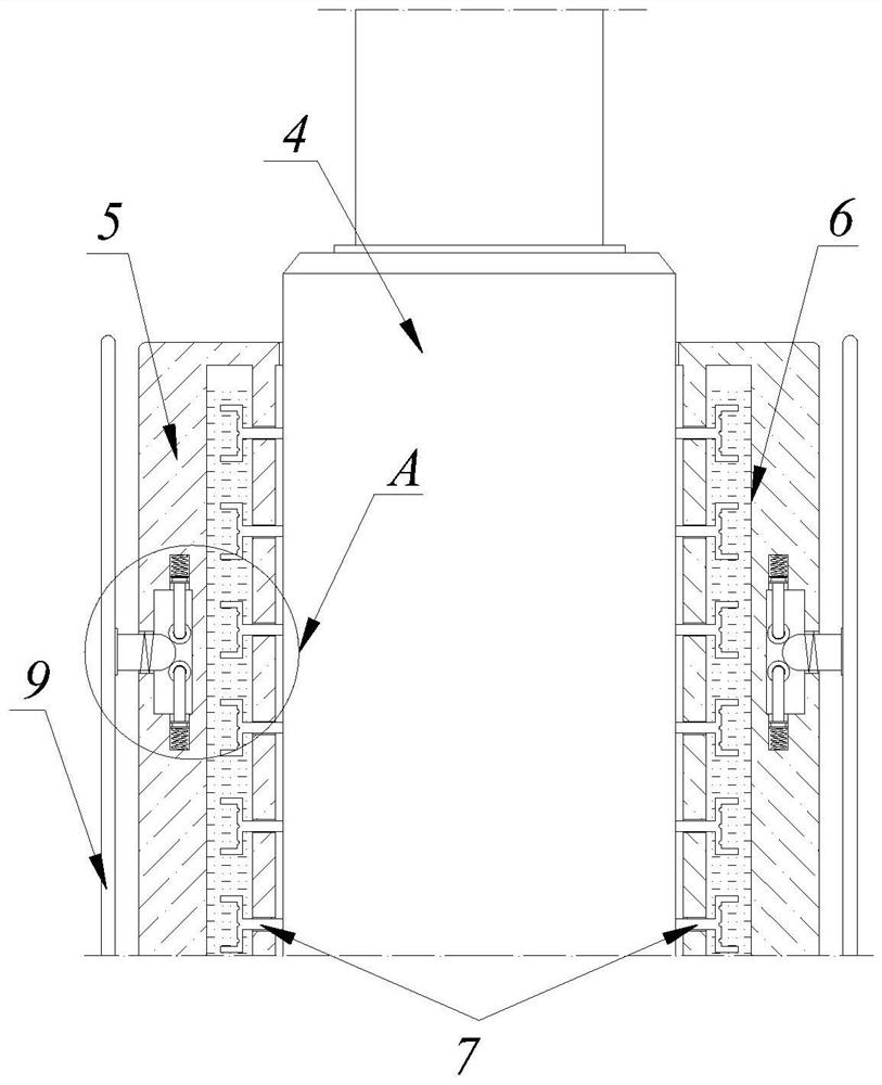
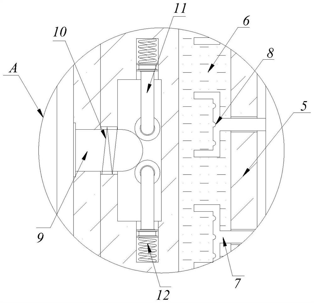
[0032] see Figure 1-5 , the present invention provides a technical solution: an automatic lifting hydraulic device for an excavation trolley, comprising an excavation trolley main body 1, a guardrail 2, a mobile base 3 and a hydraulic lifting cylinder 4, the upper end of the excavation trolley main body 1 A protective fence 2 is installed on the side, and a mobile base 3 is installed on the side of the lower end of the excavation trolley main body 1, and the ...


PUM


Abstract

The invention discloses an excavation trolley automatic lifting hydraulic device which comprises an excavation trolley main body, a protective guard, a movable base and a hydraulic lifting cylinder, wherein the protective guard is installed on the side of the upper end of the excavation trolley main body, and the movable base is installed on the side of the lower end of the excavation trolley main body; and the movable base is connected with the lower end of the excavation trolley main body through the hydraulic lifting cylinder. The device also comprises a protective sleeve arranged at the outer side of thehydraulic lifting cylinder, wherein a cooling cavity filled with cooling liquid is formed in the inner side of the protective sleeve, and a heat absorption conduction sheet is inserted into the cooling cavity; and a barrier plate which is installed on the side of the protective sleeve, wherein the barrier plate and the protective sleeve are connected with each other through a built-in spring providing reset elastic force. According to the excavation trolle automatic lifting hydraulic device, the good heat dissipation and cooling effects can be achieved in the using process, the temperature of oil in the hydraulic cylinder is prevented from being too high, and meanwhile a certain buffering and protecting effect can be achieved after collision occurs.

Description

technical field [0001] The invention relates to the technical field related to excavation trolleys, in particular to an automatic lifting hydraulic device for excavation trolleys. Background technique [0002] The excavation trolley plays an irreplaceable position during tunnel excavation, providing a working platform for workers during drilling, charging and arch installation. The movement of the tunnel excavation trolley at the construction site mainly depends on the push of the loader. When digging, the ground is not flat and fixed, and it also relies on pad stones. The poor stability leads to safety hazards and it is time-consuming to move each time. When the lithology of the tunnel deteriorates, the construction method of two-step excavation becomes three-step excavation. When excavating, the upper part of the excavation trolley is basically in contact with the tunnel vault, and the remaining construction space is narrow, which is not conducive to construction and the m...

Claims


Application Information

Patent Timeline
Patent Type & Authority Applications(China)
IPC IPC(8): B66F11/04B66F17/00F15B21/0423
CPCB66F11/04B66F17/00F15B21/0423
Inventor 陶铁军田兴朝谢财进贾健姜远坤
Owner GUIZHOU UNIV
Why Eureka
Try Eureka