Ground torque swing range determination method and drill column torsional pendulum sliding well drilling method

A determination method and ground technology, applied in the determination of the ground torque swing range, in the field of drill string torsional sliding drilling based on the ground torque swing range, can solve the problem that the ground torque and the screw torque action area cannot intersect, the anti-support pressure effect is not obvious, The design of clockwise torque is too small to avoid serious problems of supporting pressure, improve sliding drilling efficiency and drilling speed, and improve the level of anti-drill string supporting pressure.

Pending Publication Date: 2022-02-08
BC P INC CHINA NAT PETROLEUM CORP +1
View PDF2 Cites 0 Cited by
  • Summary
  • Abstract
  • Description
  • Claims
  • Application Information

AI Technical Summary

Problems solved by technology

For example, one of the objectives of the present invention is to provide a method for determining the swing range of ground torque in sliding drilling, so as to overcome the inability of the ground torque and the screw torque action area of ​​the torsion control technology to intersect, resulting in a relatively small design clockwise torque and poor anti-backup effect. Obvious issues

Method used


Image

  • Ground torque swing range determination method and drill column torsional pendulum sliding well drilling method
  • Ground torque swing range determination method and drill column torsional pendulum sliding well drilling method
  • Ground torque swing range determination method and drill column torsional pendulum sliding well drilling method

Examples


example 1

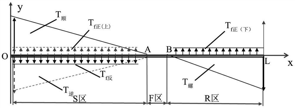
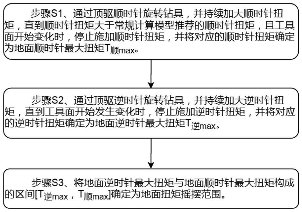
[0150] In order to realize precise control of the torsional force on the ground and give full play to the drag reduction effect of the torsional force on the ground, the present invention provides a simple and fast method for determining the swing range of the ground torque.

[0151] The method includes the following steps:

[0152] (1) When the top drive rotates the drilling tool clockwise, first apply the clockwise torque according to the clockwise torque value recommended by the conventional calculation model, and then continue to increase the clockwise torque by superimposing 150N.m each time until the clockwise torque is When it is applied to cause the lower drilling tool to start slowly (that is, the tool face starts to change), stop applying the clockwise torque, and determine the corresponding clockwise torque as the maximum clockwise torque on the surface T 顺max .

[0153] (2) When the top drive rotates the drilling tool counterclockwise, continue to increase the cou...

example 2

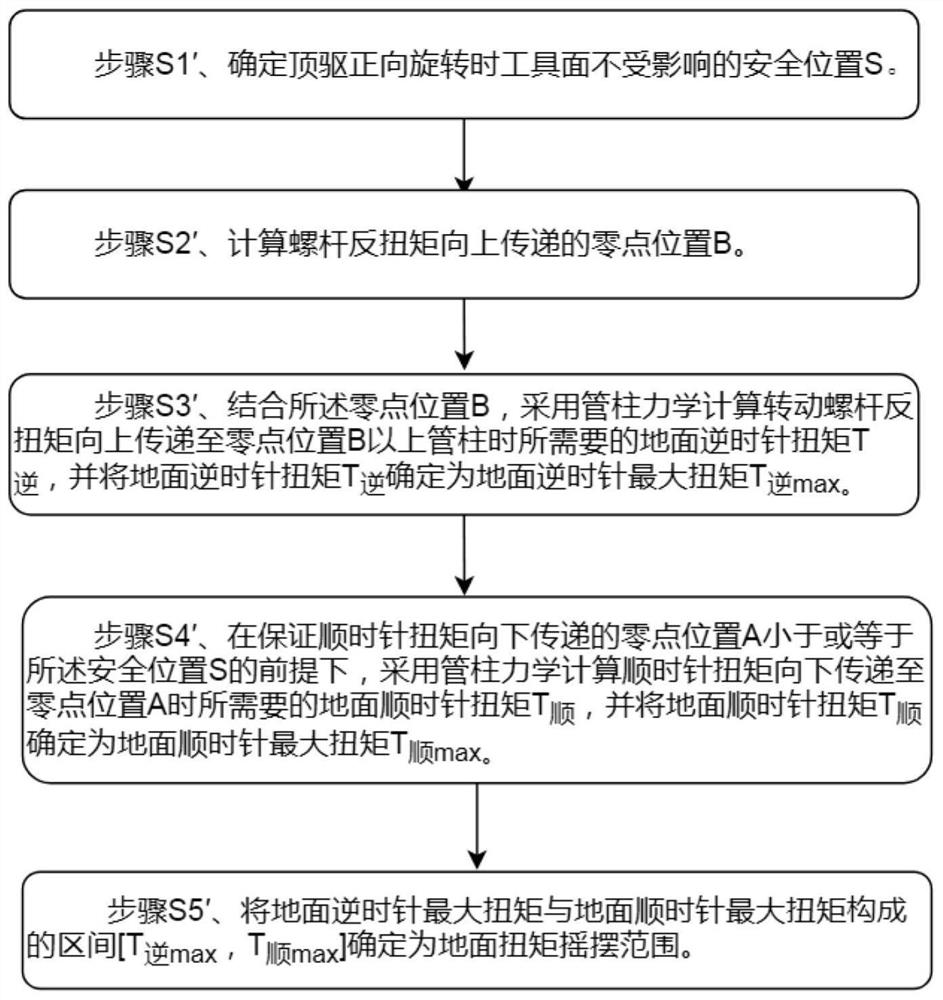
[0156] Such as Figure 6 As shown, a sliding drilling system includes a screw drilling tool 1 , a downhole drill string 2 and drilling equipment 3 . In order to improve the drilling efficiency and drilling speed of drill string torsional sliding, this example provides a method for determining the surface torque swing range.

[0157] In this example, a method for determining the ground torque swing range may include the following steps:

[0158] (a) Analyze the drill tool assembly and determine the safe position S where the tool face is not affected.

[0159] (b) Calculate the zero position B of the upward transmission of the screw reaction torque.

[0160] (c) Calculate the counterclockwise ground torque and determine the maximum counterclockwise ground torque.

[0161] (d) Calculate the ground clockwise torque and determine the maximum ground clockwise torque.

[0162] (e) Determine the range of ground sway torque.

[0163] In step (a), the structure of the drill string ...


PUM


Abstract

The invention provides a ground torque swing range determining method and a drill column torsional pendulum sliding well drilling method. The determining method comprises the steps of continuously increasing a clockwise torque during forward rotation till the zero point position A of downward transmission of the clockwise torque is located in the reaction torque acting area of a screw drill, and when the screw drill at the shaft bottom starts to be started, stopping applying the clockwise torque, and determining a zero position B of upward transmission of the reaction torque of the screw drill under the inertia effect after the clockwise torque disappears when the ground clockwise maximum torque is obtained and reverse rotation is performed; and obtaining a ground anticlockwise maximum torque, and determining an interval formed by the ground anticlockwise maximum torque and the ground clockwise maximum torque as a ground torque swing range. The drag reduction effect of ground torsional force can be fully exerted, the problem that supporting pressure of a static friction area is serious during sliding drilling is avoided, and the torsional sliding drilling efficiency and the drilling speed of a drill column are improved.

Description

technical field [0001] The invention relates to the technical field of oil and gas drilling engineering, in particular, to a method for determining the swing range of ground torque, and a drill string torsion sliding drilling method based on the swing range of ground torque. Background technique [0002] At present, there are mainly two technologies to realize the expected drilling of directional wells and horizontal wells in formations: one is rotary steerable drilling technology, and the other is sliding drilling technology. Among them, sliding drilling technology is the current domestic mainstream directional well and horizontal well trajectory control means. The advantage of this method is that the cost is lower, compared with conventional drilling, only the downhole dynamic drilling tool and the measurement-while-drilling instrument are added; the disadvantage is that during the sliding drilling process, the drill string above the drill bit does not rotate, and can only...

Claims


Application Information

Patent Timeline
Patent Type & Authority Applications(China)
IPC IPC(8): E21B7/04E21B7/10E21B44/04E21B47/00G06F30/27G06Q50/02
CPCE21B7/04E21B7/10E21B44/04E21B47/00G06Q50/02G06F30/27
Inventor 连太炜刘伟陈东许期聪郑海波冯思恒张萍寇明杨瑞帆高林
Owner BC P INC CHINA NAT PETROLEUM CORP
Why Eureka
Try Eureka