Tail gas purification system for fuel train

A technology for exhaust gas purification and trains, which can be used in exhaust devices, combustion engines, internal combustion piston engines, etc., and can solve problems such as life-threatening safety, poor combustion conditions, and insufficient fuel combustion.

Pending Publication Date: 2022-02-08
无锡市隆盛轨道科技有限公司
View PDF0 Cites 0 Cited by
  • Summary
  • Abstract
  • Description
  • Claims
  • Application Information

AI Technical Summary

Problems solved by technology

[0002] Fuel trains usually use diesel engines to generate electricity to drive motors to drive locomotives. The exhaust gas has a large displacement, and the exhaust gas emits a large amount of harmful and polluting substances such as carbon monoxide, hydrocarbons, nitrogen oxides, and particulate matter during operation, especially in the engine of fuel trains. When starting up, because the best combustion conditions are not reached, the fuel combustion is not sufficient, and the concentration of particulate matter in the exhaust gas is high. This particulate matter is a serious carcinogen and will cause great harm to people.
The concentration of nitrogen oxides emitted by fuel trains is very high, which will cause acid rain and seriously damage the environment
[0003] At present, the internal fuel locomotives do not use exhaust post-treatment devices to treat the exhaust gas. The exhaust gas is directly discharged into the atmosphere through the chimney. In the railway tunnel with poor ventilation conditions, the combustion conditions are poor and the concentration of exhaust pollution is extremely high due to the lack of oxygen in the intake air. It even caused great harm to the personal health of flight attendants, maintenance operators and passengers, and even endangered life safety in severe cases.
And for higher environmental protection requirements in the future, the use of diesel locomotives without exhaust after-treatment devices will be severely limited

Method used


Image

  • Tail gas purification system for fuel train
  • Tail gas purification system for fuel train
  • Tail gas purification system for fuel train

Examples


Embodiment 1

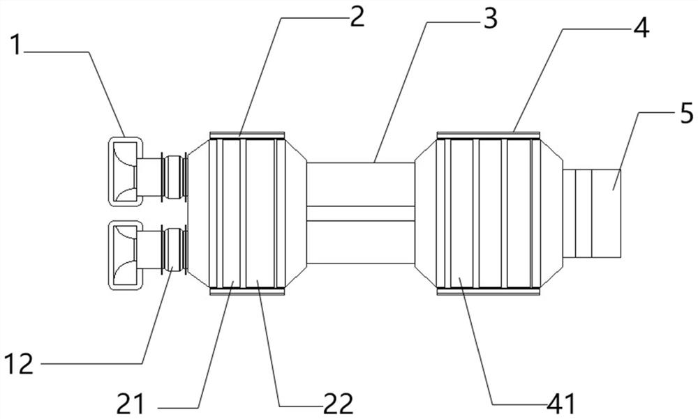
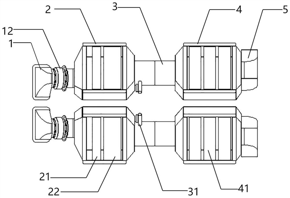
[0028] Such as figure 1 As shown, a fuel train exhaust gas purification system is characterized in that it includes an intake unit 1, a catalytic oxidation filter unit 2, a urea mixing chamber 3, a catalytic reduction unit 4 and an exhaust unit 5, and the entire purification system is installed on the train On a fuel engine, wherein the air intake unit 1 is connected to a turbocharger.

[0029] As a possible implementation, the air intake unit 1 is directly connected to the exhaust port 11 of the engine, and the exhaust gas of the engine is introduced into the exhaust gas purification system, and the exhaust gas will pass through the catalytic oxidation filter unit 2, the urea mixing The chamber 3 and the catalytic reduction unit 4 are finally discharged from the exhaust unit 5 .

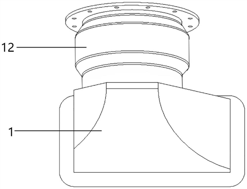
[0030] Such as image 3 As shown, as a possible implementation, the air intake unit 1 and the catalytic oxidation filter unit 2 are connected by a section of bellows 12, since the entire purificat...


PUM


Abstract

The invention provides a tail gas purification system for a fuel train. The tail gas purification system is characterized by comprising a gas inlet unit, a catalytic oxidation filter unit, a urea mixing cavity, a catalytic reduction unit and a gas exhaust unit, wherein the gas inlet unit is directly connected with an exhaust port of an engine, tail gas exhausted from the exhaust port of the engine sequentially passes through the gas inlet unit, the catalytic oxidation filtering unit, the urea mixing cavity and the catalytic reduction unit and is finally exhausted from the exhaust port, the catalytic oxidation filtering unit comprises a DOC carrier (a diesel catalytic oxidizer) and a DPF carrier (a diesel particulate filter), and the catalytic reduction unit comprises an SCR carrier (a selective catalytic reduction unit). According to the invention, the SCR carrier is added to treat nitrogen and oxygen pollutants, so purified engine tail gas reaches a higher environmental protection standard; and the DOC carrier, the DPF carrier and the SCR carrier can be conveniently detached, replaced and maintained, so the service life of the whole purification system is guaranteed.

Description

technical field [0001] The invention relates to the technical field of exhaust gas treatment, in particular to an exhaust gas purification system for fuel trains. Background technique [0002] Fuel trains usually use diesel engines to generate electricity to drive motors to drive locomotives. The exhaust gas has a large displacement, and the exhaust gas emits a large amount of harmful and polluting substances such as carbon monoxide, hydrocarbons, nitrogen oxides, and particulate matter during operation, especially in the engine of fuel trains. When starting up, because the best combustion conditions are not reached, the fuel combustion is not sufficient, and the concentration of particulate matter in the exhaust gas is high. This particulate matter is a serious carcinogen and will cause great harm to people. The concentration of nitrogen oxides emitted by fuel trains is very high, which can cause acid rain and seriously damage the environment. [0003] At present, the inte...

Claims


Application Information

Patent Timeline
Patent Type & Authority Applications(China)
IPC IPC(8): F01N3/035F01N3/10F01N3/28F01N3/20F01N13/00
CPCF01N3/035F01N3/106F01N3/2892F01N3/2066F01N13/009F01N13/011Y02T10/12
Inventor 朱荣生陈迪王劲舒顾春华何昌华
Owner 无锡市隆盛轨道科技有限公司
Why Eureka
Try Eureka